1969 750 Wiring question

Simon Yates

Senior member
Sorting out the wiring, first of all get it working then tidy up. 
Got the starter, kill, main/dip, horn working.  Still the indicators and flash to sort. 
A question for you learned types - do the indicators really need the diodes connected to each side? 
 
do the indicators really need the diodes connected to each side?

Not quite sure what you mean Simon.  They are sometimes used (depending on the type of flasher relay) to support the dash repeater light by avoiding a sneak circuit to earth.  Looking at the original wiring diagrams, no they're not used.
 
You don?t need diodes with standard type indicators. Your power to the L/R flasher switch goes through the flasher relay (BEFORE the switch), then it is simply a wire to the + side of each left and right indicator, which also has to have an earth. I always use two pin electronic type relays, to avoid flash rate issues with different wattage globes.
On SF at any rate the repeater in the instrument was just a globe wired between the left and right sides (on the + side if I recall correctly), dead simple. Check the wiring diagram you find various places online. pretty sure Laverdamania site has it.
 
They're highly likely for using LED "bulbs" in the indicators. Worth it for the increased visibility. I don\t understand why the modern crop of motorcycle/motorcyclists are so insistent on having indicators that are essentially totally useless. I regard them as a vital safety feature.
Although if you're the type who never uses indicators anyway it doesn\t matter that they're not visible.

Ken
 
mcnicol said:
They're highly likely for using LED "bulbs" in the indicators. Worth it for the increased visibility. I don\t understand why the modern crop of motorcycle/motorcyclists are so insistent on having indicators that are essentially totally useless. I regard them as a vital safety feature.
Although if you're the type who never uses indicators anyway it doesn\t matter that they're not visible.

Ken

I've got the indicators attached to the end of my arms on most of my bikes  :D :D
 
phil37 said:
I've got the indicators attached to the end of my arms on most of my bikes  :D :D

You big show off, Phil, just 'cos you''ve got one of these ...  :D

18_1303910255_5381_300_300.JPG
 
If you fit LED bulbs you will need diodes for left and right sides.  You can buy these from ebay with heat sinks included, fit inside the headlight shell.  However does not save power due to load on diodes.  Using standard wiring with indicators LEDs and no diodes can mean no indication or all four indicators flashing.  Special flasher units are available for LED systems.
Regards John E
 
Led flasher units used  on my 750"s  from AES

https://www.autoelectricsupplies.co.uk/search?search_string=led+flasher&x=0&y=0


Jade750SF said:
If you fit LED bulbs you will need diodes for left and right sides.  You can buy these from ebay with heat sinks included, fit inside the headlight shell.  However does not save power due to load on diodes.  Using standard wiring with indicators LEDs and no diodes can mean no indication or all four indicators flashing.  Special flasher units are available for LED systems.
Regards John E

Hi Jade. I see that is your first post. Welcome to the forum!

The things with heat sinks that you have to fit to an indicator system are resistors, not diodes. The original flasher units that have a thermal relay in them need the correct amount of current to heat the bi-metallic strip, which makes them flash. LED bulbs don't draw sufficient current in parallel with the flasher circuit to draw additional current through the relay. You're quite correct in that it doesn't save power because most of the power drain goes through the resistor(s).

You can either have one resistor (wired to earth) between the flasher relay and indicator switch, or one on each of the left and right indicator circuits. With the original Laverda wiring system, you need a resistor on each side (left and right) otherwise the little pilot lamp won't flash.

An alternative is to buy a new solid state flasher relay that's not load dependent, but again, you'll have problems with the pilot lamp. Easiest solution to that conundrum is to choose a relay with a separate pin to drive the pilot lamp, but it'll require a change to the wiring.

The bottom line is that changing from incandescent globe to LED indicators isn't as straight forward as just swapping the globes. Google "LED indicator wiring" and you'll find plenty of info. If anybody is still confused, I could draw up some wiring diagrams.
 
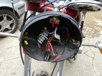
All I have to do before I arrange the MOT is succeed in positioning the headlight reflector in the shell WITHOUT pulling half the connectors apart ::).
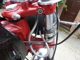
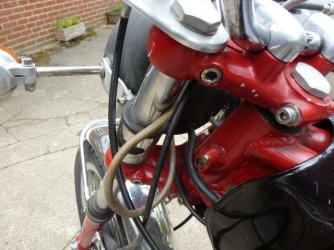
It may be worthwhile moving the connector blocks (or replacing them with waterproof ones) near to the coils.  The main loom and the Lucas switch cables are easily long enough (the Lucas cables are the grey ones in the last 2 images).  Then I can run the limited number of new longer wires to the ignition switch front indicator and front lights.  The connector blocks are a 6 way and a 5 way from the switches.  Also, the connectors are rather poor quality and need to be replaced with better ones.
I would be willing to take the bike somewhere if a good place is recommended.


Are the above recommended if I relocate the connectors?  They do 5 and 6 way as well but will need the proper crimping tool.
 

Attachments

  • P1030925.JPG
    P1030925.JPG
    168.5 KB · Views: 19
  • P1030926.JPG
    P1030926.JPG
    171 KB · Views: 12
  • P1030927.JPG
    P1030927.JPG
    167 KB · Views: 9
I agree the crimped connectors in your head light leave a lot to be desired and you should re do them. No reason why you couldn't do yourself. Think the water proof ones are a bit of an over kill however, just tidy up and replace all the dodgy ones in your shell and leave them in there.
The key is use hi quality terminals not the el cheapo's which someone has used on yours and get your self a good quality crimp tool, if you go for a ratchet one make sure it is set correctly as they can cause issues by not crimping properly.

http://www.ebay.co.uk/itm/HEATSHRINK-INSULATED-RING-TERMINAL-ELECTRICAL-CRIMP-WIRE-CONNECTOR-/281738194404?var=&hash=item4198e7ade4:m:mgOlIszVvM-z0Z0lwa1DcJw

http://www.ebay.co.uk/itm/Ancor-Single-Crimp-Ratchet-Tool-f-22-8-AWG-Heatshrink-Vinyl-Nylon-Insulated-/372062696265?epid=1438809877&hash=item56a0aa3349:g:16UAAOSwH2hZqH~0
 
Back
Top