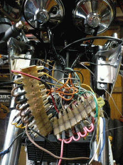
200mm headlight photos... inside

scuderia

Senior member
Location
San Francisco
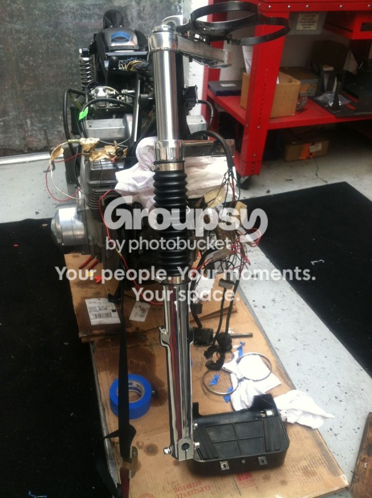
started working on the wiring today on the 3C replica....
could use a photo of the stock wiring in the 200mm headlight as a reference as to how I might arrange things....
thanks,
Don
 
k2540021.jpg
 
Don, you're a brave man. Drikko's picture shows it cleaned up a lot. It might help if you have a circuit diagram for your model, but I suspect that in 1973 bikes came off the production line as individually crafted pieces of Italian electrical engineering, each one different depending on who assembled them and how they were feeling at the time. Mine had several block junctions with 2 wires on one side, one on the other, all different colours, none corresponding to the diagram I had.

If you're doing it authentic, you'll be using 2 screw terminal junction blocks held to the inside of the bucket (one on each side) with little metal "fingers" riveted to the inside of the shell. I wish I could help more, but I used to open my 3c headlight, turn sickly white, and put it back as quickly as possible. Hopefully someone here can give you more useful information.

Ken
 
Have to agree that the photos are less than useful at times -- however when disassembling my '77 3CL I did take plenty of pictures which you can see here

Andy
 
I've been asked to rewire a Jota over here, had a look at Dartys 1200 to see how it is put together and as mentioned above it's pretty horrendous. I remember my 750 was worse though with all those junction thingys under the seat. The RGS seems relatively simple by comparison. Will be searching for some multipin connectors which are neat and small, relays for the headlights and minimalise the whole electrics. Should be able to trim down enormously on the mess with a bit of organisation. I really can't understand how they managed to make it so complicated!

It won't be done for a few months but will document it at the time.
 
guess i'm hoping to see what connectors were used inside the 200mm shell and how they differ form the ones on the 3cl harness (what i'm using) so i can see how to attach them to the shell if i can..
the bundle of wiring doesn't look too daunting but then I haven't tried to put in the shell yet.
btw, won't be using the ND switches but figure I'll get everything working first with them before i try and adapt the bosch and hella ones i've got.
forks.jpg
 
Don, take a look at http://www.laverdamania.net/wire4.htm, thanks to JLO. This is an HKZ wiring diagram, '73"ish",  showing the the 2 junction blocks I mentioned attached to the inside of the headlight shell. No barrel connectors here! Sorry, still no pictures.

Drikko, not going to use an m-unit? You seemed pretty keen on them a while back.

Ken
 
Err that brings back memory's,delicately jambing it all in and hoping nothing comes adrift or pulls apart and being very happy not having to go back in.I especially loved those plastic chocolate blocks with the multiple loops.
 
One of the beauties about the original terminals (which continued thru to at least 1977) was that they were flexible and would mould to the shape of the headlight insert so that after 4-5 hours on high beam they had melted and formed a nice homogenous mass. FUN at 11pm when you refuel and find the headlight gently smoking.
One good thing about the original terminals was that they were semi transparent and you could see the hot joints as they turned brown around the joint from the heat.

If you think a LAV is bad, have a look at a 70's Duke ! :o
 
Back
Top