3

You are using an out of date browser. It may not display this or other websites correctly.
You should upgrade or use an alternative browser.
You should upgrade or use an alternative browser.
3
3patC
Guest
Dont knoow if this is relevant to you Stefan but I had an early type cover on my 3C and I bought a new pick-up plate assembly from Wolfgang because the original pick-ups were wrecked.
When I came to fit it I found the later plate and the early cover weren't compatible. The design must have been subtly changed at some point.
Regards Pat
When I came to fit it I found the later plate and the early cover weren't compatible. The design must have been subtly changed at some point.
Regards Pat

jotacorsa
Hero member
- Location
- between Santa Fe and Taos
stefan, i'm inclined to believe the later style inlet and outlet windows covered with punched sheet metal insert works best. it does, however, let in more weather. the original outer covers had a drain hole. i've seen two different replica covers (not gavin's) without the drain boss drilled. #2367 has the ~10mm holes, #5136 has the two windows. i'll see if i can get some images and measurements for you.
pat, my 3C had an alloy spacer between pickup plate and inner cover. seems it was mislaid/lost over the years the machine was in boxes
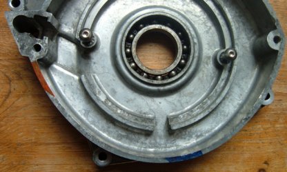
when i finally got the engine together i discovered the same problem. later covers had the inner cover trimmed/relieved on the raised boss supporting the oil seal for coil clearance. if one scribed four marks 0,90, 180, 270 degrees then trimmed the two quadrants beneath the coils
i swear i saw my spacer a of couple years ago ...i said ah ha and put it where i knew i could find it. haven't seen it since ...
i think the change was about the time the fully alloy encased pickups went away ...maybe from the 100W to the 123W trickle charge system and the spacer was used until older stock inner covers were used up
cheers,
scott
pat, my 3C had an alloy spacer between pickup plate and inner cover. seems it was mislaid/lost over the years the machine was in boxes
when i finally got the engine together i discovered the same problem. later covers had the inner cover trimmed/relieved on the raised boss supporting the oil seal for coil clearance. if one scribed four marks 0,90, 180, 270 degrees then trimmed the two quadrants beneath the coils
i swear i saw my spacer a of couple years ago ...i said ah ha and put it where i knew i could find it. haven't seen it since ...
i think the change was about the time the fully alloy encased pickups went away ...maybe from the 100W to the 123W trickle charge system and the spacer was used until older stock inner covers were used up
cheers,
scott

I think Bosch experienced electrical shorting issues with the first version of the pick-up plate. It was susequently thickened at the area described by Scott with more insulation and the inner cover altered to suit. I've come across several bikes where the owner had not noticed(didn't care?) the subsituted parts were not compatible and just tightened the plate down, with it either warping or cracking as a result.
Not sure if the Bosch alternator really needs more or less fresh air except perhaps in extreme climatical conditions. Reckon all holes could be blanked off on bikes running in bleak northern Europe...
The dreaded workshop black hole strikes again!
piet
Not sure if the Bosch alternator really needs more or less fresh air except perhaps in extreme climatical conditions. Reckon all holes could be blanked off on bikes running in bleak northern Europe...
jotacorsa said:i swear i saw my spacer a of couple years ago ...i said ah ha and put it where i knew i could find it. haven't seen it since ...
The dreaded workshop black hole strikes again!
piet

troutbishop
Hero member
- Location
- Worcestershire England
My 3C special has a non vented case and is tucked away behind a Cico fairing where it doesn't get much air flow. Do you think it would be better to vent it in some way? I do have an old outer cover that I could vent to help keep things cool ??
Kev
Kev

mcnicol
Hero member
- Location
- Safety Harbor, Florida, USA
Stefan, I tend to agree with you. My '73 3c had a single drain in the outer cover only, but I took the bike in all sorts of places in northern Australia the Laverda boys would never have dreamed the bike would go, rode in continuous tropical downpours for hours on end, endless very dusty dirt roads etc. I didn't see any reason to introduce muddy water and dirt to my ignition/charging system so I plugged the drain up and sealed the cover with silicon.
Accumulated heat possibly made the life of the HKZ pickup wires even shorter, but I don't think a single 8 or 10mm hole in the bottom of the outer cover would have made much difference. Frankly, aside from the fact that the bike could be push-started and run normally with a flat battery, it was a pretty poor design (I only had the single 100W power coil too) and I would have replaced it if a better option was available while I still owned the bike. To be fair, the initial HKZ design was pretty good for an early '70s race bike and did everything that was needed for the track, but didn't meet the needs of sport tourers. The Series 2 electrical system fixed many of the problems, and they would have continued to improve, just like they did with everything else (except dropping the 180 crank : ).
Ken
Accumulated heat possibly made the life of the HKZ pickup wires even shorter, but I don't think a single 8 or 10mm hole in the bottom of the outer cover would have made much difference. Frankly, aside from the fact that the bike could be push-started and run normally with a flat battery, it was a pretty poor design (I only had the single 100W power coil too) and I would have replaced it if a better option was available while I still owned the bike. To be fair, the initial HKZ design was pretty good for an early '70s race bike and did everything that was needed for the track, but didn't meet the needs of sport tourers. The Series 2 electrical system fixed many of the problems, and they would have continued to improve, just like they did with everything else (except dropping the 180 crank :
).Ken

Hey Boba,
We have been fooling around with temperature recordings on both the Series 1 and Series 2 engines, specifically the ignition area.
Not done a 120 engine as all their owners tell me they are so cool so no need to record how hot they get which to me sounds like a load of crap.
Is a bit difficult to record an average temperature, it all depends on ambient temperature to start with, how long you ride in what conditions, if you are up the engine or cruising, etc
Lots of variables.
Series 1 is running around 75-95C, is very dependant on ambient temperature
Series 2 is approx 5C higher temp wise then a Series 1
Is why we went away from the Optical triggers on our ignitions, Hall Effect triggers have a higher temperature rating and are more robust
HTH
Red
We have been fooling around with temperature recordings on both the Series 1 and Series 2 engines, specifically the ignition area.
Not done a 120 engine as all their owners tell me they are so cool so no need to record how hot they get which to me sounds like a load of crap.
Is a bit difficult to record an average temperature, it all depends on ambient temperature to start with, how long you ride in what conditions, if you are up the engine or cruising, etc
Lots of variables.
Series 1 is running around 75-95C, is very dependant on ambient temperature
Series 2 is approx 5C higher temp wise then a Series 1
Is why we went away from the Optical triggers on our ignitions, Hall Effect triggers have a higher temperature rating and are more robust
HTH
Red

IIS
Full member
Hello Lads and Red,
What fun to be had at the end of a Laverda crank, well fun has many forms.
Did extensive work on the heat issues to be dealt with on the IIS applications for not only Laverda, Moto Guzzi and Ducati also. Made a batch of hall effect sensors in the base shape of a Bosch reluctor pick up. Embedded in the pickup was a temperature sensor chip. Logged temperatures on the 120 motors and the 180 II's, did something different on the 180 series 1 motor however. First the Ducati, being a bevel, the pickup was in the crank case oil ie inside the crankcase. This S2 Ducati ( 1000 ) registered 120C inside the motor in stalled traffic on a very hot day. That is oil damage temperature and was typical for air cooled engines operating in Australian summers. Take note, it is hot out here.
120 motors were not too bad, something like a 50C differential between ambient and normal operating motor riding. Stalled traffic could see 90C or more in the timing cavity. Extreme days, over 100C. 180 series 1 were a different game all together, the reasons were not clear to me for the most part. Many of the usual components and adhesives did not last in the series 1 motors. Most damaging of all was the hot contaminated oil, over time. Reason why the wires fail in the series 1 bosch systems. The actual potted bosch 180 reluctors rarely fail, compared to lead in wiring. The "BTZ" style pickups however pull the centre pole faces, as many know here. That is a temperature problem for that pickup design, ie the plastic deforms over time.
Long storey short, the production IIS test jig could heat the Hall effect crank encoders up to 150C at cold crank speed to 6Krpm, response of encoders noted on a CRO to verify pulse shape specification to operate the control board correctly. Not only that, the crank encoder has to operate at least to 0C also, one IIS tested in the USA started the Laverda engine at about minus 28C, and unconfirmed minus 43C, way beyond the operating range of many semi conductors on the open market. While the IIS hall effect crank encoder board seems to be simple, many was the conflicting design problem to overcome. Then there is the vibration.... did i talk of the vibration..... and the shaking of components..... walking away scratching head.....and bum..... grin.
*BTW tested all the variations of cutouts on the series 1 alternator cover and inner casting, all rely on the motor in an air stream to work. Stuck way out there as it is... it is the stalled traffic condition that presents the most demands on design criteria.
HTH John.
What fun to be had at the end of a Laverda crank, well fun has many forms.
Did extensive work on the heat issues to be dealt with on the IIS applications for not only Laverda, Moto Guzzi and Ducati also. Made a batch of hall effect sensors in the base shape of a Bosch reluctor pick up. Embedded in the pickup was a temperature sensor chip. Logged temperatures on the 120 motors and the 180 II's, did something different on the 180 series 1 motor however. First the Ducati, being a bevel, the pickup was in the crank case oil ie inside the crankcase. This S2 Ducati ( 1000 ) registered 120C inside the motor in stalled traffic on a very hot day. That is oil damage temperature and was typical for air cooled engines operating in Australian summers. Take note, it is hot out here.
120 motors were not too bad, something like a 50C differential between ambient and normal operating motor riding. Stalled traffic could see 90C or more in the timing cavity. Extreme days, over 100C. 180 series 1 were a different game all together, the reasons were not clear to me for the most part. Many of the usual components and adhesives did not last in the series 1 motors. Most damaging of all was the hot contaminated oil, over time. Reason why the wires fail in the series 1 bosch systems. The actual potted bosch 180 reluctors rarely fail, compared to lead in wiring. The "BTZ" style pickups however pull the centre pole faces, as many know here. That is a temperature problem for that pickup design, ie the plastic deforms over time.
Long storey short, the production IIS test jig could heat the Hall effect crank encoders up to 150C at cold crank speed to 6Krpm, response of encoders noted on a CRO to verify pulse shape specification to operate the control board correctly. Not only that, the crank encoder has to operate at least to 0C also, one IIS tested in the USA started the Laverda engine at about minus 28C, and unconfirmed minus 43C, way beyond the operating range of many semi conductors on the open market. While the IIS hall effect crank encoder board seems to be simple, many was the conflicting design problem to overcome. Then there is the vibration.... did i talk of the vibration..... and the shaking of components..... walking away scratching head.....and bum..... grin.
*BTW tested all the variations of cutouts on the series 1 alternator cover and inner casting, all rely on the motor in an air stream to work. Stuck way out there as it is... it is the stalled traffic condition that presents the most demands on design criteria.
HTH John.