no spark on 1979 Jota

rob reznik

New member
Hi - I'm new here so please be gentle with me!!

Owned a series 1 1979 Jota for about 7 years now and decided to do a refurb powder coating frame etc. about 3 years ago. Only just got to the stage of putting it back again and having issues getting a spark on the middle cylinder - its BTZ standard electrics.

I can get sparks on the two outer cylinders but the spark is weak (Coils on the way out maybe?) - no spark on the middle one - if I swap the black/red trigger wires over I can get a spark and its a good one on the center one but nothing on the outside two. I suspect the right hand electronic module faulty but not sure as I can't check it as its a sealed unit. I've had a look on past posts here and cannot find one becoming faulty which is why I'm questioning it. There is voltage to both trigger wires which is only about 1V on the one that seems to work and 11.5V on the duff one.

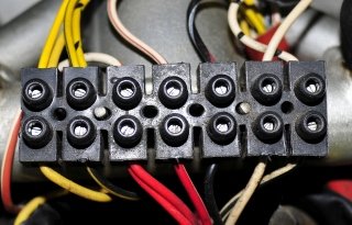
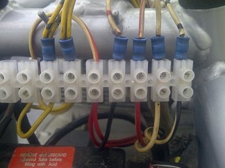
I'm also not 100% sure I have wired the 'block' right so here is a photo - I think something may have been changed at some stage as a couple of the wires seem to be the wrong colour.

Any help would be appreciated and there is a sense of urgency with this as I don't live in the UK and wanted to get the bike finished and sold before I return in about a month.

I'm currently in Wolverhampton if anyone has any spare parts I could check with or buy.

Thanks in anticipation.

Rob 
 

Attachments

  • jota wiring.jpg
    jota wiring.jpg
    32.3 KB · Views: 34
at least the terminals are not crimped on very well... restrip the wires, use new amps and use a good amp crimper (top example, the bottom one makes very bad connections)
crimpers.jpg

about the right connections... I'm not into Laverda wiring yet but with the wiring schedule you could trace if everything is connected correctly
http://www.laverdafinland.org/cape/kuvat/jota%20wiring.jpg
 
Hi Rob
I think you've crossed at least one wire on that terminal block.  Hopefully it won't have cooked the BTZ amplifier box!  Most wires, including the ignition trigger wires, should go colour-to-colour across the terminal block. 

So (numbering from the right of the block and working left) that means (1) black/white to black/white and (2) white to white as you show in the photo for the centre cylinder amplifier is OK. 

The next pair of trigger wires - according to the diagram I'm looking at -  should be white/red/black and white/red respectively.  Can't match that from your photo...not enough length visible?  If those crimped wires all come from the alternator - worth checking! - then they must be OK.  Does the bottom of terminal 3 have a red/white wire or just red?  Terminal 5 has a red/white wire at the top - that should connect to the same colour on terminal 3 or 4. 

The yellow and yellow/black wires are alternator output and look OK.

Just leaves the live feed to the resistors (have they been removed?) and then on to the HT coils.  This is red on one side of the terminal block and originally orange/white on the other. Here's a link to part of the wiring diagram which may help you sort this.
http://www.laverdaforum.com/gallery/albums/userpics/10040/Series_1_BTZ.pdf

Oh - and TinTin is right! - those crimps look very suspect.  We're talking very low voltage and current from the triggers and decent connections are a must (once you've got the right connections!)  Good luck
 
Ok - thanks for the replies - yes all terminals need sorting properly but I dont think thats the problem at the moment.

As I mentioned the wiring is not the same as the manual and I suspect things have been changed in the past. Main culprit is the black/red/white wire that should be coming from the RH module is in fact black and there is no black/red/white wire from the alternator. - I know the photo is small but looking from the bottom of the photo and from right to left the wires are
1. black/white stripe
2. white
3. red/white stripe
4. black ( this should be black/red/white )

from top of photo again reading right to left
1. white/black blobs
2. white
3. white/red stripe
4. white/red blobs


here is a link to photobucket which should show the bigger photo but I can take more http://s989.photobucket.com/albums/af16/sreznik/?action=view&current=IMG-20120528-00006.jpg

I have swapped 3 and 4 over but makes no difference.

I have the same wiring diagram which shows the left module controling the right coils - I'm assuming this is correct?

power to ballast resistors are looped orange/white followed by orange (LH) and green (RH)

trigger wires are red/black to both but are bullets so can only really go to the correct sides and these havnt been changed

Thanks again
 
Hi Rob,
When I saw you'ed powder coated the frame,the first thing I thought of was 'EARTH'.
Have you got a good earth connection between the frame and batttery and also engine and frame?
Ideally you need to remove the powder coating from say the bottom engine mounting point on the chain side.Also the battery earth strap needs to be connected to a point minus powder coating.
I'd check your earth before doing anything esle!

Andy
 
good point Andy - took all powdercoating off all earths to frame (with flapper) but didnt do the engine - could this really make a difference to sparks on just one side? - I'll do it later though anyway. 
 
you could run a temporary wire from the battery ground to the engine (case, cilinders) doesn not really matter as long as the connection is good. I usually run one from the cilinder fins to the minus battery terminal using a emergency battery booster cable... Morini 3 1/2 have the same grounding problems with the engine case / frame. is the emergency cable works you could run a permanent cable to one of the casings bolts
 
OK - so just to clarify.  You can confirm that these wires

from top of photo again reading right to left
1. white/black blobs
2. white
3. white/red stripe
4. white/red blobs
 

definitely disappear off to the alternator?  

Can you measure the resistance between 1 & 2; also 3 & 4 with the wiring to (or) the modules disconnected. Also between each of the 4 wires and earth. Might be as well to disconnect battery negative before you do that just in case the wiring is horribly wrong! Certainly check there is no voltage on any of those 4 wires to earth.

If the wiring has been changed to one of the modules, I'd wonder why and what sort of connection has been made to do that.  The modules are identical and can be swapped one for the other to confirm healthy.

Good point on earthing Andy!
 
wires all go to alternator - traced them down -

1. to upper left trigger (connected to small black wire)
2. to upper left trigger (connected to small white wire)
3. to lower right trigger (connected to small black wire)
4. to lower right trigger (connected to small white wire)

will check resistance later when near bike

thanks again
 
 
Its strange that the poor quality blue connectors were used at all, even in the absence of good connectors and a ratchet crimper - just tightening the terminal block screws down directly onto the bare wires twisted together would be 100% better (and onto bare wires twisted and soldered together 200% better)..
 
G'day Rob, and welcome to the forum.

As Brian says, ditch the crimp connectors altogether. Simply poke the ends of the stripped wires into the sockets on terminal block screw connectors. Better still, if you have a soldering iron, tin the ends of the wires with a dab of solder to stop them fraying and to give the connector screw something to bite on. The solder also helps to prevent oxide forming on the copper wires if the bike is exposed to a salty environment (like the salted roads in UK).

When you come to sell the bike, let us know. You're very likely to find a buyer on this forum who will give you a fair price. Even if you can't get it running properly with the BTZ ignition, you'll still be able to sell it as it is, and it probably won't make a lot of difference to the sale price anyway. Most of us replace the old ignition systems even if they are working because later ignition systems are so much better. So having BTZ ignition is not really a desirable selling point!

Cheers,
Cam
 
FWIW...

I've always been told - by both electronics and electrical techs - that you should never solder a wire that you intend to crimp or clamp. The reason is that solder will gradually cold-flow under pressure, resulting in an eventual loosening of the joint.

If you want to solder a crimped joint, always do it after crimping. 

In the case of the typical Laverda clamp terminal block, the best thing is a bootlace ferrule.  This is a soft metal sleeve which groups and protects the stranded conductor wires from damage due to the turning action of the clamp screw.

In the absence of those, the best option is to snip a few mm from the end to remove the corroded/damaged wire and strip back the insulation and twist by hand.  No solder.

cheers
SteveB
 
Spot on Steve.  Hopefully will save a few of our number from electrical gremlins - usually at the roadside and at night  :'(
 
Fair enough Steve. Everyone has their preferred method of doing things. I agree that soldering prior to clamping can introduce another failure mode, but I've come to the conclusion that the advantages outweigh the disadvantages - especially if you're like me and always fiddling with things, so the connections get undone and re-done a bunch of times. Doing that on non-soldered wire ends ends up with the copper all frazzled and thinned out from busted strands. After you've stripped back chewed off wire ends a couple of times you might run out of length. I solder crimped terminations too (after crimping) because it makes the joint more secure. I've had wires pull out of un-soldered crimps, even on the original factory made joints.

I developed my habit of tinning or soldering joints from wiring boats.

It's normal practice when wiring boats to tin all wire terminations. As well as protecting the copper, it helps block moisture propogation along the wire by capiliary action. I did my boat like that over 20 years ago and nearly all of the wires terminate in screw connectors (something like a couple of hundred terminations). Not a single termination has failed in that time, even in places where they are exposed to weather or salt water spray like navigation lights.

Non-tinned terminations fail reasonably quickly in a marine environment because the copper gets green oxide on it and sometimes rots away completely (I've had to fix poorly wired boats for friends). When you cut the wire back to make a new termination, the copper has a black oxide coating inside the insulation because the salty moisture has wicked it's way up the wire. You often have to cut a metre or so off the wire to find clean copper, which usually means there's not enough length in the wire. The only thing the old wire is good for in that case is pulling in a new wire.

You can buy marine grade wire with a pre-tinned core but it's bloody expensive and hard to find in a useful range of sizes.

I acknowledge that bikes aren't generally subject to such a chemically agressive environment as boats, but they have a tougher mechanical environment (engine and road vibration). I figure I may as well make my wiring joints as robust as possible. I can't swear on a stack of bibles that I've not had a joint fail, but honestly I can't recall any. 99% of dodgy wiring I've had to fix has been somebody else's - and the problem is usually crappy terminations.

Cheers,
Cam
 
wire ferrules crimped on with the right equipment are required by the dutch railroad in their equipment to prevent loosening of the wire due to vibration of the train. Guess that will also do for our bikes  ::)
http://www.specialtycontrolsystems.com/wire_ferrules/wire_ferrules.php
ferrules.jpg

tlcrmp-16174b.jpg


Back
Top