Regulator/ rectifier issues

martymoose

Hero member
Hi guys,

As you know I have just fitted the new upgraded IIS  ignition with a Honda stator  to my 3C. The charging rate across the Battery with the headlight off is between 14.6 and 15 V  depending on revs.  With the headlight on I am getting 15.8 V. I believe the rectifier has shit itself. I have purloined a new rectifier off a Suzuki from work , But I have an extra wire. Has anyone had experience in setting up a modern rectifier with four wires going into the loom.  I have two red and two black wires, three stator wires I can work out.  Need positive and negative and the signal wire to a switch circuit, what is the fourth wire for, the warning light?
 
Yes. I've come across RRs with two red and two black wires. They are just duplicates to increase the Ampere capacity without having to use thicker wires. I guess they did it that way to keep individual wires thin enough to bend around wherever they wanted to put them.

Just treat the two reds as the same positive wire and the two blacks as the same negative.
 
Hi cam,  yes i agree, which works on the suzuki setup.  On my old setup i had a brown wire running to the fuse box, what i believe is a sensing wire.  Not needed with the suzuki rr?
 
Sorry Marty, I mis-read your question. I thought you were confused by the proliferation of red and black wires.
Yes, you're right about the red, black and brown being positive, negative and voltage sense respectively. If you have a fourth wire on the DC side, it's a bit of a mystery.

I can only think of two possibilities:

1. An output for an indicator light. I've seen a few single phase RRs with a generator light output. Never seen or heard of a 3-phase RR with one though.

2. A power supply for a field coil in the alternator. If that's the case, the thing may not work with your 3C. You say that it has a Honda stator, but I presume it has a permanent magnet rotor, not a field coil. For a permanent magnet alternator you need a shunt regulator rather than a field coil regulator.

What's the make/model of the RR? There should be a manufacturer's ID somewhere on it. We may be able to glean some info from that. It also might help to know what model Suzuki it came from.
 
Suzuki gsx650f but they are all similar on the new bikes. 4  wires to the loom 2 + and 2 -.  No sensing wire. Part # sh811ab. Basically it's a 5 wire from with the pos and neg split into 2 wires presumably to run to different parts of the bike.
 
The 3c previously had the original charging system and a shendengen rr that John fitted. Is the original system what you call a field coil?  The new setup is a stator as I understand it. Magnets in the new flywheel so is that what you call a permanent magnet jobbie?  Electrickery eh!
 
Well, buggered if I know mate. I've googled the wiring diagram for the bike and the SH811AB regulator, none of which show any mysterious wires like you describe. I can't even find one with a voltage sensing wire.

There's a distinct lack of technical info on the SH811AB regulator. I couldn't even find it on a Shindengen website. All the pictures and diagrams I could find show an RR with 3 AC phase wires, 2 red DC positive and 2 black/white DC negative wires. Nothing else. So it appears to be a shunt regulator which would be OK for your bike.

Is the original system what you call a field coil?

No. Original alternators on Laverda triples had permanent magnet rotors with the power generating coils in the stator. Your present upgraded system is the same.  Permanent magnet alternators deliver maximum power all the time. The RR controls system voltage by shunting any excess juice from the alternator to earth. That's why they're called shunt regulators.

A field coil alternator has an electro-magnet in the rotor rather than a permanent magnet. The output of the alternator can be varied by controlling the amount of current that powers the coil in the electro-magnet, which alters the strength of the magnetic field (hence the name "field coil"). The regulator's job is to do exactly that. It feeds the right amount of current to the coil in the electro-magnet to maintain a constant voltage in the DC system.

 
Thanks cam I've learnt a lot. I'm going to delete the brown wire and connect the 2 positives and 2 negatives direct to the battery. I'm assuming that the modern rr has an inbuilt sensor and doesn't need a sensor wire.
 
The reason for the separate sensor wire is that the voltage is usually a bit lower in the wiring system "downstream" of the ignition switch than it is at the RR. That's because of voltage drop when there's loads on the electrical system.
The RR bumps the output voltage up a bit to compensate. Just measure the system voltage when you crank up the engine, if it goes up to around 14V it's OK.
 
Fixed!  14.4 v max and drops to 14.1 v with headlight on. Yeehaa!  And no Vince I'm still not getting heated grips😬
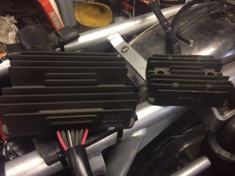
New rr is twice the size of the old sh530 which was off a Kawasaki zzr250.
 

Attachments

  • IMG_1967.JPG
    IMG_1967.JPG
    105.4 KB · Views: 23
Blimey, that's a big motherf ...

Must have a high enough current rating for a small power station. Heated grips would be no problem. You could also have a heated jacket, boots and codpiece.
 
Back
Top