Years ago, I presented an analog MAP/TPS system, which was designed by a fellow club member ltmt7. It has served well, but times change, things evolve and now it’s time to go digital.
I have designed a new module, based on programmable ATtiny85 microcontroller. Since it is digital, there is no ripple (or it is filtered) and the signal from MAP- and TPS-sensor to TCIP4 ignition unit is stable. The module can be used with Hall-effect TPS sensor or one build with potentiometer and spur gears on carburetor.
The ATtiny85 program handles MAP and TPS signals individually. The sensors must be calibrated; that is, the minimum and maximum voltage signals entered into the program must correspond to the actual readings. The program reads the voltage from the sensors and ATtiny85 analog input (ADC) coverts them into digital values between 0-1023. These values are then used for MAP and TPS scales, 0-100 %. Then the program calculates engine load percentage by combining the values and converts them to 8-bit PWM-signal between 31-204, values equal voltage between 0,6-4,0 V. The signal is a weighted average, MAP 40 % and TPS 60 %. Finally, the signal is sent to TCIP4 pin 6 via RC-filter, which converts it to stable analog DC-voltage. This all is done several times per second.
On TCIP4.exe program, the TP min. % is set to 0,6 V and max. % to 4,0 V. These voltage values are based on motorcycle standards, OEM-sensor values and Ignitech TCIP4 ignition unit sensor input safety limits. There’s no need to change these in the future.
I will make these to order. If interested, send me an email.
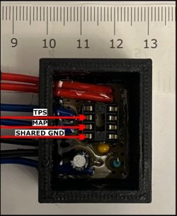
In the attached image, the microcontroller is not in place, but the sensor measurement points on its carrier are visible.
Cheers,
Sami
I have designed a new module, based on programmable ATtiny85 microcontroller. Since it is digital, there is no ripple (or it is filtered) and the signal from MAP- and TPS-sensor to TCIP4 ignition unit is stable. The module can be used with Hall-effect TPS sensor or one build with potentiometer and spur gears on carburetor.
The ATtiny85 program handles MAP and TPS signals individually. The sensors must be calibrated; that is, the minimum and maximum voltage signals entered into the program must correspond to the actual readings. The program reads the voltage from the sensors and ATtiny85 analog input (ADC) coverts them into digital values between 0-1023. These values are then used for MAP and TPS scales, 0-100 %. Then the program calculates engine load percentage by combining the values and converts them to 8-bit PWM-signal between 31-204, values equal voltage between 0,6-4,0 V. The signal is a weighted average, MAP 40 % and TPS 60 %. Finally, the signal is sent to TCIP4 pin 6 via RC-filter, which converts it to stable analog DC-voltage. This all is done several times per second.
On TCIP4.exe program, the TP min. % is set to 0,6 V and max. % to 4,0 V. These voltage values are based on motorcycle standards, OEM-sensor values and Ignitech TCIP4 ignition unit sensor input safety limits. There’s no need to change these in the future.
I will make these to order. If interested, send me an email.
In the attached image, the microcontroller is not in place, but the sensor measurement points on its carrier are visible.
Cheers,
Sami