1000 triple 180 clutch wire functioning

Enrico

New member
Location
Italy
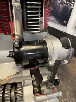
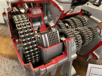
I have a question about the clutch wire and more specifically how it works.
The wire is connected on the right side of the motor assembly, while the clutch disks are engaged / disengaged on the left side.
Clear for me the working principles of the clutch of course, not how the wire on the right is capable to compress the springs on the left.
Thanks to everyone who can explain this detail to me.
 

Attachments

  • IMG_6387.jpeg
    IMG_6387.jpeg
    193.7 KB · Views: 22
  • IMG_6391.jpeg
    IMG_6391.jpeg
    164.6 KB · Views: 18
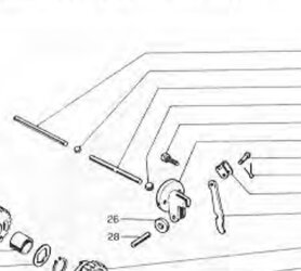
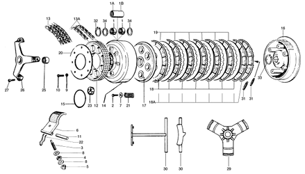
Adding something. The manual shows these parts. Steel rods and balls but not sure where they go to compress the springs.
 

Attachments

  • IMG_8320.jpeg
    IMG_8320.jpeg
    203.6 KB · Views: 6
Thank you Paul for your clarification.
Where the rods are installed? Inside the axis part #35?
Not sure why are provided the two steel balls and why they have a different size.
Moreover, the square bar part #27 is installed at the left end of the axis part #35? Is there a groove or something to keep it in position? Maybe the two retaining rings are installed to keep the bar in position avoiding to go out.
I am not able to find pictures that explain the actual installation.
 
The rods go through the gearbox shaft n°35 with a steel ball in the middle. I don't remember the respective size of the steel balls.
The other ball, part n°12 is under the lifter mechanism 48.
The bar 27 isn't maintained other than by the rod 30 which limits it's mouvement in part n°17 below.
1704461250548.gif
 
The ball in between the two rods is about the same dimension as the rods, the bigger ball at the right hand end sits in the release mechanism in the engine cover. This system and variations on it is quite common in many bikes of the period, not just Laverdas.
The bar sits inside a hollow in the pressure plate, you have to be careful that it stays there when assembling the clutch.
 
Thank you all for the great explanations that are leading me to fully understand the system.
The only thing that remains unclear to me is how the rectangular bar #27 is held in position towards left. On the right side of course the position is maintained by the steel rod #30.
Look at the snipshot attached taken from the workshop manual. Quality is bad but shows the bar #27. How it stays in position and doesn’t fall towards left?
 

Attachments

  • IMG_8324.jpeg
    IMG_8324.jpeg
    87.5 KB · Views: 12
When the clutch is assembled the bar is located in the pressure plate on the left, and the rods on the other side, there is not enough clearance for it to dislodge. If you temporarily fit in place the bar, the pressure plate, and rods without installing the springs, you can push on the rod protruding from the RH end of the gearbox and you will see how it pushes out the pressure plate.
 
The imperial sized ball bearing is to mitigate the fast rotating clutch drum from the stationary actuation mechanism, prevent
friction welding together, that may be obvious or no. Hope that helps. j
 
Thank you all for the very complete explanations.
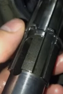
I’ve found also the attached picture that shows a slotted through hole that explains without doubts where the bar#27 is located.
The explanation of the steel balls makes a lot of sense now.
I don’t have any other question.
All the best.
 

Attachments

  • IMG_8326.jpeg
    IMG_8326.jpeg
    54.2 KB · Views: 21
Back
Top