1977 3C wiring diagram

Rob3CL

New member
Location
Phillip Island
Hi Everyone,
Not sure if this is the correct place to put this, so if I'm posting incorrectly, my apologies and to the forum admin, please feel free to move to a more accessible spot.

I have been working on replacing (and understanding) the original wiring on my 1977 3C, while the engine is off being rebuilt. (Nearly there! I should have the engine back in another week or 2 and actual rebuilding can begin, yay!)

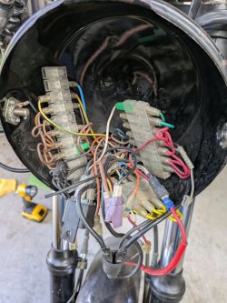
Anyway, while I was trying to understand the bike's original wiring, I looked inside the headlight shell, this is what I found...

So, I thought about this for a while. (I have previously restored several 1100 Suzuki Katanas, early 1980's models and was not expecting wiring like this!) After searching and finding a few wiring diagrams, which I had enlarged to A3, I thought this would help.

The problem was the coloured lines were so thin, even enlarged, and using a magnifying glass, I couldn't properly differentiate between, like orange and brown etc.

So I sent the wiring diagram, which I'd sourced from this site (thanks heaps for it!) to someone who was able to make the coloured lines much thicker. Then I had this enlarged to both A3 and A2.

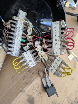
I also devised a system of labelling the existing wiring before I removed it from the headlight shell, that is shown in the 2nd photo. (It made sense to me so I hope it works when I go to reassemble it all.)
Something I have noticed, is that the existing wiring in the headlight shell, does not really accurately follow the wiring diagram. So, when I start connecting ti back up I'm thinking I will follow the wiring diagram.

Also a question to those waaay more expert than myself in matters Laverda. The small black relay in the bottom of the 2nd photo, is that the engine stop switch? The wiring diagram places this near the regulator and the battery.

(I think I've just attached the Wiring diagram with thicker coloured lines, although it isn't displaying an my screen in all its coloured glory, mmmm? Perhaps I need to do something else??
So, a BIG thank you to this group for providing the initial diagram that enabled me to get it enlarged.
Cheers
 

Attachments

I don't think that relay is the stop relay... looking at the colours of the wires I reckon someone has added it to minimise the current through the ignition switch. In turn this will alter the standard wiring arrangement so unless you want to remove that relay you'd be better to retain the non standard arrangement.

It's also apparent that an earth wire has been added to the headlight shell. May be worth shortening the adjacent bolt to avoid snagging adjacent wiring.

The stop relay (if it's the later torpedo type) will be hanging from the main loom under the tank. Dunno where they fitted the original square relay that interrupts the alternator ac output (red wire) to the HKZ black box.

Seems you went to a lot of trouble with the wiring diagram. ILOC's Ted Aves produced a superb set of coloured wiring diagrams. I'm doing a similar job to yours on my '77 and find it invaluable. They're available to members in the iloc.co.uk library.
 
Last edited:
Welcome Rob,

nice job with the wiring diagram.

LAVs are pretty good in the wiring, especially compared to other Italian bikes and some Japanese bikes.

In my experience, the biggest problems are:
1. previous owner changes
2. wires broken within the loom sheath around the headstock
3. changes to the handlebar mounted switchgear, meaning different wire colours and possibly dodgy solder joints
4. corrosion in the connectors and the fuse block.
5. failure of the ignition switch due to current draw through it.

As Bob states above, the relay shown is not standard, so the wiring will need chasing out.
The addition of a relay that the ignition switch controls is worthwhile, but will need a small amount of rewiring.

A good improvement to make IMHO is to run an earth wire from the headlight back to the battery -ve terminal, and continue on to the tail light.
A good bolted connection at those 3 points and connecting your earth (common in fact) wires at those points can improve the electrical system, especially when it comes to reliability. Don't rely on an earth/-ve/com connection across the head races. Murphy's first law of relativity is alive and well.

I would re-instal the wiring/new wiring exactly as you found it, rather than 'correct' it to the factory drawing. At one time we had 4 3CL's, 2 x 1976, 2 x 1977. Popping the headlight out of the shell had different coloured wires connected to the same terminal/connectors in the headlight shell on all 4.

A nicely renovated 3CL is a beautiful bike, especially in the mid green some came in, and a damn fine ride.

ENJOY.

DavidH
 
Welcome Rob,

nice job with the wiring diagram.

LAVs are pretty good in the wiring, especially compared to other Italian bikes and some Japanese bikes.

In my experience, the biggest problems are:
1. previous owner changes
2. wires broken within the loom sheath around the headstock
3. changes to the handlebar mounted switchgear, meaning different wire colours and possibly dodgy solder joints
4. corrosion in the connectors and the fuse block.
5. failure of the ignition switch due to current draw through it.

As Bob states above, the relay shown is not standard, so the wiring will need chasing out.
The addition of a relay that the ignition switch controls is worthwhile, but will need a small amount of rewiring.

A good improvement to make IMHO is to run an earth wire from the headlight back to the battery -ve terminal, and continue on to the tail light.
A good bolted connection at those 3 points and connecting your earth (common in fact) wires at those points can improve the electrical system, especially when it comes to reliability. Don't rely on an earth/-ve/com connection across the head races. Murphy's first law of relativity is alive and well.

I would re-instal the wiring/new wiring exactly as you found it, rather than 'correct' it to the factory drawing. At one time we had 4 3CL's, 2 x 1976, 2 x 1977. Popping the headlight out of the shell had different coloured wires connected to the same terminal/connectors in the headlight shell on all 4.

A nicely renovated 3CL is a beautiful bike, especially in the mid green some came in, and a damn fine ride.

ENJOY.

DavidH
Thank you to Rob and David for their thoughtful and informative responses, much appreciated. I will certainly add the earth connection in as I've had situations previously where an 'extra' earth has helped solve gremlins.
That is very interesting about apparent lack of standardisation across Laverda models!
 
Thank you to Rob and David for their thoughtful and informative responses, much appreciated. I will certainly add the earth connection in as I've had situations previously where an 'extra' earth has helped solve gremlins.
That is very interesting about apparent lack of standardisation across Laverda models!
Welcome to Laverda. It was a small town concern.
They went bust trying to standardise.
Paul
 
That’s news to me, please elaborate.

Marnix
Standardisation was part of the process of trying to move into the big boys market rather than keep producing the products that made Laverda successful, rather like Guzzi did.
Laverda was commercially successful when it was a back garden industry, with all of it's idiosyncrasies and lack of standardisation.

Paul
 
Mechanical person(s) ( factory ) designing electrical systems, becomes very obvious quickly, once you work on your first Laverda electrical harness and basic switching. Obvious design flaw number one, using the steel frame and attached electrics as a reliable conductor. May have been of use in the early 1900's not for the later 1900's as copper was expensive. More so using the aluminium crank case(s) as a starter motor conductor of several hundred amps, aluminium oxide being a very good insulator ( 300V withstand or better ).

MG LeMans MK3, "nul" wiring termination on various wire connectors, ie a short link on one side of the connector returning the wire back into the originating harness, a good idea to a mechanic, lack of basic electrical understanding more the matter. So it goes, yet why complain, i know i dont, offer remedies, cannot be more thankful to bosch for the rudimentary "electrics" of oem, overall reliable as it was, yet performance was also rudimentary or less, 90W for an alternator output, on a 981cc motor.... grimace. Ripe for proper electrical design and best performance replacement system or parts. Which the dedicated few/odd bods supply j.
 
Hi Everyone,
Not sure if this is the correct place to put this, so if I'm posting incorrectly, my apologies and to the forum admin, please feel free to move to a more accessible spot.

I have been working on replacing (and understanding) the original wiring on my 1977 3C, while the engine is off being rebuilt. (Nearly there! I should have the engine back in another week or 2 and actual rebuilding can begin, yay!)

Anyway, while I was trying to understand the bike's original wiring, I looked inside the headlight shell, this is what I found...

So, I thought about this for a while. (I have previously restored several 1100 Suzuki Katanas, early 1980's models and was not expecting wiring like this!) After searching and finding a few wiring diagrams, which I had enlarged to A3, I thought this would help.

The problem was the coloured lines were so thin, even enlarged, and using a magnifying glass, I couldn't properly differentiate between, like orange and brown etc.

So I sent the wiring diagram, which I'd sourced from this site (thanks heaps for it!) to someone who was able to make the coloured lines much thicker. Then I had this enlarged to both A3 and A2.

I also devised a system of labelling the existing wiring before I removed it from the headlight shell, that is shown in the 2nd photo. (It made sense to me so I hope it works when I go to reassemble it all.)
Something I have noticed, is that the existing wiring in the headlight shell, does not really accurately follow the wiring diagram. So, when I start connecting ti back up I'm thinking I will follow the wiring diagram.

Also a question to those waaay more expert than myself in matters Laverda. The small black relay in the bottom of the 2nd photo, is that the engine stop switch? The wiring diagram places this near the regulator and the battery.

(I think I've just attached the Wiring diagram with thicker coloured lines, although it isn't displaying an my screen in all its coloured glory, mmmm? Perhaps I need to do something else??
So, a BIG thank you to this group for providing the initial diagram that enabled me to get it enlarged.
Cheers
Great wiring diagram and it is correct, but it is for the 1975 European version only.
 
Great wiring diagram and it is correct, but it is for the 1975 European version only.
Thanks for the info, that actually makes sense as this bike was imported privately from Europe a few years ago. So no wonder this particular wiring diagram makes some sense to me when I look at the layout of my bike. Yay, a bit of a win there then!
Cheers
Rob
 
Back
Top