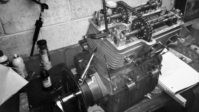
4C Cam install 1200

Open and close figures are usually quoted (and measured) at ~1mm lift for the reasons already pointed out.  For setup purposes they are sort of not that important themselves, rather the midpoint between them (the lobe centre).
As with others, I always work to a lobe centre figure, only using the open and close points as a way to determine the centre.  For someone only doing it occasionally, it just seems much simpler.

It can get confusing if you're changing around your measurement references, ATDC, BBDC, etc, so if my lobe centre is quoted ATDC then I take the measurements relative to that (might be a silly number).
Alternatively, there is a convenient calculator and useful background reading on the following page:
https://www.rbracing-rsr.com/camshaft.html
That will spit out your lobe centre based on your measured 1mm lift open and close points to the nearest typical reference (same as in Rusty's earlier post).  Lobe centres to aim for are stated by Dellortoman.

HTH
 
"I am rotating the engine and setting the dial gauge at zero when it is fully closed. The just rotating back until it hits zero and recording the number on my wheel."

Engine must always be turned forward ( the direction it turns when it's running) to get a meaningful figure. Slack, in the drive will give false figures if turned back.

"I'm taking my valve readings off of the right cylinder."

Phil recommends using "I always check the timing at maximum lift on the lobe furthest from the camwheel" ie. the left cylinder.
 
breganzane said:
Open and close figures are usually quoted (and measured) at ~1mm lift for the reasons already pointed out.  For setup purposes they are sort of not that important themselves, rather the midpoint between them (the lobe centre).
As with others, I always work to a lobe centre figure, only using the open and close points as a way to determine the centre.  For someone only doing it occasionally, it just seems much simpler.

It can get confusing if you're changing around your measurement references, ATDC, BBDC, etc, so if my lobe centre is quoted ATDC then I take the measurements relative to that (might be a silly number).
Alternatively, there is a convenient calculator and useful background reading on the following page:
https://www.rbracing-rsr.com/camshaft.html
That will spit out your lobe centre based on your measured 1mm lift open and close points to the nearest typical reference (same as in Rusty's earlier post).  Lobe centres to aim for are stated by Dellortoman.

HTH

This....This is how to do it. Trying to work off the point of max lift - and assuming it's the center of the lobe opening period is useless. There is no requirement for the cam lobe to be symmetrical. Frequently they're not.
The point at the center of the opening period is the lobe center. As an abstract figure, comparisons of lobe centers across different engines are valid. Comparison of the point of max lift tells you nothing.

Zero your dial gauge at valve closed. Read the degree wheel at .040 - or 1.0mm - lift. This gets you past any quietening ramps. The valve clearance doesn't matter, you'll get an accurate lobe center figure regardless of clearance.
 
Good explanation, Greg. The max open concept I used came from V2 in Perth when I first set my SF up for adjustable cam timing about 35 years ago. Your (and Steve's) system actually looks easier and more accurate.
 
The Sock said:
Phil recommends using "I always check the timing at maximum lift on the lobe furthest from the camwheel" ie. the left cylinder.

I can't see how it would make any difference which lobe you use. It's not as if there's going to be any measurable twist in the camshaft. It's not a torsion bar.
 
Dellortoman said:
I can't see how it would make any difference which lobe you use. It's not as if there's going to be any measurable twist in the camshaft. It's not a torsion bar.

One thing that is useful when doing this job especially on bikes with pressed-up cranks is to dead stop each cylinder and check the crank phasing is correct, and to also check lobe centres on each cylinder to make sure they are ground at exactly 120/180 degrees for a triple/500, and especially on the multi-piece 750 cam to check how far from 180 the two sides are.

If you have some variation you can then decide the best compromise to use as a reference when setting it up and on the 750, whether you need to faff about degreeing-in each side.  My 750 racebike was based on an original splined centre which had a couple of degrees between the two sides, so I modded things such that I could degree in each cam to it's corresponding cylinder.
 
breganzane said:
One thing that is useful when doing this job especially on bikes with pressed-up cranks is to dead stop each cylinder and check the crank phasing is correct, and to also check lobe centres on each cylinder to make sure they are ground at exactly 120/180 degrees for a triple/500, and especially on the multi-piece 750 cam to check how far from 180 the two sides are.

If you have some variation you can then decide the best compromise to use as a reference when setting it up and on the 750, whether you need to faff about degreeing-in each side.  My 750 racebike was based on an original splined centre which had a couple of degrees between the two sides, so I modded things such that I could degree in each cam to it's corresponding cylinder.

I have a piece of silver steel of the appropriate OD and length for checking 4 cylinder Suzuki GS/GSX cranks. At points 180 degree  apart, all 4 small ends should line up. Quick and dirty - but accurate enough.
Having just spent time setting up the cam in an XR500 honda, I must ask, when dialling in the SOHC twins, do you do it at running clearance ?
Like the Honda, the point of contact rocker to cam, changes with differing clearances. Doing it at zero clearance won't be the same as running clearance.
The bloody CB350 twins are a prick to get right. The eccentric rocker spindles can go either way - and sometimes have to, lol.
 
If you wanted to get all nth 'degree' (no pun intended) with a the SOHC SF cams, you could cut each half in half and set it up so the exhaust and inlet could be adjusted independently!! A bolt through the middle to hold the two halves together?!!?
 
Last night I did not get to spend much time with the bike. I did print out the C4 specific degree wheel. I then attached it to my larger HotCams wheel. It certainly helps to have the timing of each cam staring me in the face while I rotate the engine.
 
Ok,,back to this project on this snowy day. Heat and radio both cranked up here in my micro shop.
I have been rotating and notating for most of the afternoon.
I am aiming for the note on the laverda mania page that states "advance ex by 4-7 and retard intake by 2-4. "
That tells me that my opening numbers should be  around 46-48 in. and 74-77 ex.

Well , I have the ex close , reading 75 deg at opening-
Intake is not going so well. I cant get any closer than 68 for an opening number. So I am nowhere near the 50 that the factory calls for, never mind the recommended - 46-48.

Both flanges are slotted a bit. The intake flange has been slotted a small amount, but the ex flange is very slotted.

So, I either have an intake cam that is horrible, or the more likely scenario is that I am not doing it correctly.  I am tempted to just get it as close as I can at this point but I am concerned with piston to valve clearance. I do not want to damage the engine !
 
Please take note of the recommendations previously offered... e.g.

You need to identify the lobe centre angle at maximum valve lift. As Quentin said earlier, the best way to do that is to measure the same lift position on both sides of the cam lobe and work out the centre between those two readings. Choose a point at about half valve lift to get away from the opening and closing ramps. It's exactly the same logic as you used to find TDC. For a 4C cam, lobe centres are: Intake 102? ATDC; Exhaust 106? BTDC.
 
Hi
      First thing. Switch the radio off, no offence but you really need to concentrate. You need a dial indicator with at least 12mm of travel set on the cam bucket so it measures the opening of the valve. For you to achieve this the pointer (stylus) on the indicator needs to be about 60mm long and no more than 2.5mm diameter so the cam doesn't clomp it as it rotates. It's fiddly but absolutely necessary that the readings repeat themselves. TOTALLY IGNORE opening and closing figures, you are measuring the maximum opening of the valve. Slowly rotate the engine forward, watching the indicator, until it stops moving. Record the figure. Slowly rotate the engine backwards at least 90 degrees and then forward again to maximum opening again. The reading absolutely needs to repeat. Now VERY slowly continue to rotate forward until the indicator starts to move. Stop, record the figure and repeat. The two figures you have recorded will probably be about 4 degrees apart, known as the dwell. Maximum lift is the difference between the two recorded figures.
Compare your measured maximum lift to the one you are aiming for and REALLY think which way it needs to be moved. Remember the camwheels run at half engine speed so if you need to advance 5 degrees, the camwheel needs to move backwards 2.5 degrees. Think of your timing disc as a clock face so advancing is sooner or earlier and retarding is later as you rotate the engine clockwise. Now do the other cam, fun innit?
 
BobSol said:
Hi
      First thing. Switch the radio off, no offence but you really need to concentrate. You need a dial indicator with at least 12mm of travel set on the cam bucket so it measures the opening of the valve. For you to achieve this the pointer (stylus) on the indicator needs to be about 60mm long and no more than 2.5mm diameter so the cam doesn't clomp it as it rotates. It's fiddly but absolutely necessary that the readings repeat themselves. TOTALLY IGNORE opening and closing figures, you are measuring the maximum opening of the valve. Slowly rotate the engine forward, watching the indicator, until it stops moving. Record the figure. Slowly rotate the engine backwards at least 90 degrees and then forward again to maximum opening again. The reading absolutely needs to repeat. Now VERY slowly continue to rotate forward until the indicator starts to move. Stop, record the figure and repeat. The two figures you have recorded will probably be about 4 degrees apart, known as the dwell. Maximum lift is the difference between the two recorded figures.
Compare your measured maximum lift to the one you are aiming for and REALLY think which way it needs to be moved. Remember the camwheels run at half engine speed so if you need to advance 5 degrees, the camwheel needs to move backwards 2.5 degrees. Think of your timing disc as a clock face so advancing is sooner or earlier and retarding is later as you rotate the engine clockwise. Now do the other cam, fun innit?

Thanks for this. For some reason this is the explanation that made the most sense to my feeble mind.
I think I was getting most tripped up by two things.
My degree wheel was cut into four sections rather that 360 degrees. Some numbers were going up when they were supposed to be going down and vise versa.
Also I had it in my head that the dial indicator was representing numbers , when ( if I have this correct), it is just an arbitrary indication of when the valve is completely open. The numbers on the indicator are meaningless here and the only numbers that matter are the ones one the degree  wheel.

So, with all hat being said and a bit of free time to go out into my micro shop (with the radio off) I have some new numbers .

Again, I am aiming for these numbers from the laverda mania page :
"Example for triples equipped with 4C cams: For good mid range and no loss of top end power, a 4/C cam can be set with 4-7 advance on exhaust and 2-4 retard on Inlet. This can cure mid range problems - especially with a 3 into 1 exhaust - also gives more valve to valve clearance."

So that should be 104-106 lobe center on intake and 102-99 on ex.
If I am doing it correctly , I now have my ex lobe center set to 101 , and my intake is 107.5. I could not get the intake any closer without removing the cam and filing the holes and just dont want to do that at this point. I am hoping that 107 is acceptable and that I will have no piston/valve clearance worries.
 
Hi
    Well it looks like you now have meaningful measurements. Well done. Your choices now are fairly straightforward. The exhaust timing is fine but the inlet is a little retarded. You either take the time to elongate the mounting hole or you put it all back together and try it, if the local climate will allow. Bear in mind accurate valve timing is only one ingredient to a sweet motor and the figures quoted by Phil Todd are based on his vast experience and refer to the 1000cc motor using a three into one exhaust. Double check the timing chain tension and record valve clearances before closing up. The new cams will totally change the power characteristics of your bike and you may not like the changes but clean carburation and smoother ignition advance curves available now should do the trick if you persevere. I don't claim to be a Laverda "expert", far from it, but I'm in the process of improving the valve timing on my bike so I can relate to your grief. Have fun
Bob.
 
Good day yesterday. Closed her back up and gave it a run. I am happy to say it did not swallow a valve and runs. 
I do have an old Laverda racing 3 into1 on it that will be coming back off to fab up a baffle. The open meg sounds fun but does squat for good running.
Also it has velocity stacks. I imagine I will be having great fun with jetting from here. But that will be another thread.
 
Back
Top