750SF2 - compression ratio measures and calcs

mikeb

New member
Location
new zealand
I’m going slightly mad trying to measure (with fluid) and calculate compression ratios for my 750SF2. I keep getting a figure of approx. 17:1. They are JE pistons, 80.5 dia, fairly crowned, but surely not that much. Not sure if it’s my measures or maths – harder with the spigots.

Does anyone have some figures for the SF head chamber they can share? Including the space in the head for the spigot it fills at about 52cc. less the spigot area the chamber becomes about 30cc [EDIT - WRONG! see below]. As for these piston domes, I measure them at about 13cc (in the greased cylinder, fluid in, calcs from the spigot top to the piston edge...)
I think I have accounted for the base gasket, head gasket and remaining small area above the spigot.

Any data I can compare with would be appreciated.
thanks
 
Last edited:
Unless you're building a methanol-running Speedway bike, 17/1 is insane. Something ain't mathing.
 
Hi, working backwards on a standard 80x74 bore and stroke with a Laverdamania quoted compression ratio of 8.9:1 gives a clearance volume of 47cc, that will go up or down depending on the piston crown shape, cr being swept plus clearance divided by clearance, so if your 52 head volume was correct that would be around 8.25:1 so maybe it's the 52 minus 13 of the piston dome = 39 giving cr of 10.6:1 but there's also the head gasket, not sure how that alters it if at all, also depends on whether piston stroke brings you to the point where the 13 goes wholly into the 52
 
I had 81mm pistons, and checking the compression ratio with fluid with the head in place and torqued down gave 45cm3 volume which is 9.3:1. I find that the simplest way to measure it, motor on the bench tilted with the spark plug hole highest point, fluid part way up the plug hole.
 
Yep, only ever done it with a burette and a mix of kero (paraffin) and oil. As Tippie said, head and gaskets fitted and torqued, fill to around halfway up the plug hole. Calculate swept vol: pi x 1/2 bore squared x stoke PLUS the vol of the chamber. Divide this total by the chamber figure and that's your CR. Definitely the most accurate method. My original SF measured at 8.5:1, so the factory figure is misleading. You can bump it up a little by using a thinner base gasket - easy to make.
 
thanks for the comments and data. the goal here may be to lower compression, not raise it. currently the head and barrels are off tho rest of the lump is in the frame.
i've again remeasured (and remeasured...) tho using a 10ml syringe rather than buretee which may not be the most accurate.

this time i get a CR of about 12 - still very high but at least more plausible. the engine didn't pink as such, tho knocks under load. which i assume is the forged piston's short skirts and larger bore tolerances. the CR numbers account for
  1. a base gasket (.8mm->4cc),
  2. a small volume within the head's spigot recess (0.2mm->1cc) when accounting for the 1.3mm thick head gasket,
  3. of note 0.35mm (2cc) from the piston deck to the top of the liner spigot (at TDC, excluding the base gasket) - see pic 1. the only other pic i can find of installed 750sf pistons is this: https://laverdaforum.com/attachments/pistons-png.94923/ of Ross forged pistons and i assume atTDC with a base gasket. this looks a few mm below the top lip?? the compresson distance of these JE pistons is quoted as 34.11, almost exactly standard
so..
  • I wonder if the the barrels have been skimmed? any thoughts on pic 1 re deck height (noting no base gasket)?
  • or the the head for than matter. the spigot recess into the head measures 3.95mm (pic 2) - about right?
thanks
 

Attachments

  • 20260905_122540.jpg
    20260905_122540.jpg
    133.3 KB · Views: 30
  • 20260905_120556.jpg
    20260905_120556.jpg
    138.4 KB · Views: 29
I reckon your CR calc or measuring system is wrong. You've got at least 1mm swish with the base gasket taken into account, and that is not a particularly high dome. I've attached a few pics. Ignore the Ross OS piston on the left (not relevant), but the first pic shows a std SF Mondial (supposedly 9:1 if you ignore the 1mm removed from the swish), the second is a '74 SFC (supposedly 10:1). Your piston crown looks pretty similar to the SF slug to my eyes., so no way are you running 12:1.

Ross-Mondial.SF.JPGRoss-Asso.SFC.JPG
 
Your pistons look like they are the 1974 SFC ones which should give a compression of 9,8:1. Here is a similar picture of the engine of one of my 1974 SFCs with pistons at TDC. Yours look like the piston tops are flush with the spigots, where originally they should be below them.

Marnix
 

Attachments

  • IMG_2499.jpeg
    IMG_2499.jpeg
    308.8 KB · Views: 16
Thanks again for further comments and pics. I’m doubting my methods as well, tho I explained them and calcs to an actual engineer who agreed on the logic, and I measured again (and again) this time with kero and different syringes. It’s a weird approach to maths, but I can’t massage the CR calcs to be less than 11.6:1. (my initial 17 was a clear error)

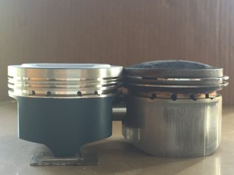
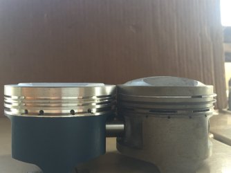
See the pic montage below of my JEs then your SFC (I’d read they were 10.5:1?), Ross, then Mondial. All a bit sketchy tho the pics are scaled to the same dia and suggest the JE crown is at most very slightly taller than the SFC. Also interesting the skirts aren’t much shorter on the JEs. FWIW I’ve asked JE if they have crown volume data on this piston, and Wolfgang also (who supplied the PO), tho it is 20 years old (the bike having negligible use in that time being in a ‘collection’ and likely coz its strange noises).

I continue to measure the actual chamber (above the spigot recess) at 39 - 40cc (max). the valves (pic2) have actual seats which may intrude a few cc, and the head may have been skimmed a little – the spigot recess is just under 4mm and there are possibly machining marks visible. and as you say the pic in previous post shows the negligible deck to spigot lip when no base gasket.

At this stage I might just fit a 1.2mm spacer under than barrels - that should get it to 10:1. And contemplate shaving some metal off the piston crown. I’ve never done that before tho there’s over 13mm of metal to gnaw away at. And rather a soft old engine on the road than a stressed one in the shed.
 

Attachments

  • piston comparison.jpg
    piston comparison.jpg
    42.1 KB · Views: 9
  • 20260906_142841.jpg
    20260906_142841.jpg
    188.3 KB · Views: 7
If you fit a 1.2mm spacer below the barrels you will really struggle to join the cam chain
 
Is there any poss you're not adding the chamber volume to your total displacement before dividing by the chamber volume? It's a common mistake when measuring CR and it will give a false high reading. I don't think your valves look any deeper into ther chamber than std. The SFC ex valve will give to a very small increasy in CR, but not from 10:1 to 11.6:1.
 
If you fit a 1.2mm spacer below the barrels you will really struggle to join the cam chain
If it's a used cam chain you might be OK - and if the head's been skimmed, that will help. The depth from the head surface to the flat swish area should tell you whether it's been skimmed - I don't have that figure for a std head, so can't help there.
 
A lot of complication going on. Why not just fit gaskets and torque the head down and check the volume. Then it is easy to swap gaskets or other modifications to get it to your desired volume. From memory one mm alters it one compression point. While you are doing that you can also easily check clearance to the valves on overlap, and squish. Or you can try to calculate a series of volumes.
 
What he said. You don't even need to use a new head gasket - any old gasket that's the correct thickness will do - then pull the head and barrels off, set your base gasket and job done.
 
yeah, i've made it complicated as the head/barrels/cover gaskets i got (rubber coated? centauro brand), had been on there torqued for literally 10 miles, glued themselves to the faces and ripped apart on disassembly. hence i'm waiting for more in the mail and not wanting to sacrifice those to an experiment. but i agree that measuring actual assembly would be less error prone and vexing...
 
I think you’ve measured the piston dome wrong. I would fit piston/ rings in barrel and lower piston to just below deck height, make it exactly so many millimeters by using a DTI. Grease ring to get oil tight seal grease a Perspex lid with a small hole for adding diesel. Fill void below Perspex with no bubbles and note volume. If you were 5mm down bore, you know what 5mm of displacement is so subtract your measured volume to give you your positive piston dome displacement. This can then be subtracted from combustion chamber volume to give a working “ compressed” volume. Swept volume of cylinder + “ compressed volume ( including gaskets) to “compressed “volume will be your compression ratio.
 
Back
Top