mikeb
New member
- Location
- new zealand
A couple of questions re head repairs.
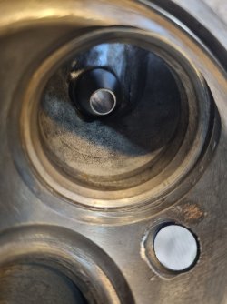
1. The camshaft tunnels are a bit scored and one or two bearings have spun a bit (see pics). I’m thinking Loctite 609 on the cam/bearings and 641 (weaker) on the scoured tunnel…. Yes? Better ideas? all bearings are being replaced - there was a slight rough patch on 1 or 2 of them
2. I’ve read about cutting the cam key in half to aid reassembly. Sounds good, as I imagine a key in place in each half will greatly assist pressing the flanges back on accurately. As the bolts do the work, is there any downside to cutting the key in half?
3. The valve seats are slightly pitted but I think look ok (see pics). Am I right that they look like a PO has replaced them? ie, they look like inserts, not 'skulls' (not that i know what a skull looks like). The valves are 7mm and look farily new to my untrained eye, and the contact / wear ring less than 2mm (tho hard to measure accurately).
Thanks!


") Far more important is the interferance fit of the flanges on the camshaft! This should be at least 0.01-0.02mm, otherwise the key/s won't last very long. Also make sure the flange and sprocket mating surfaces are dead flat to ensure adequate clamping pressure.
Far more important is the interferance fit of the flanges on the camshaft! This should be at least 0.01-0.02mm, otherwise the key/s won't last very long. Also make sure the flange and sprocket mating surfaces are dead flat to ensure adequate clamping pressure.