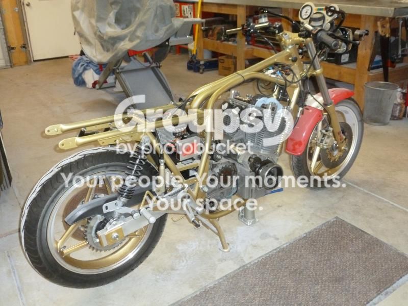
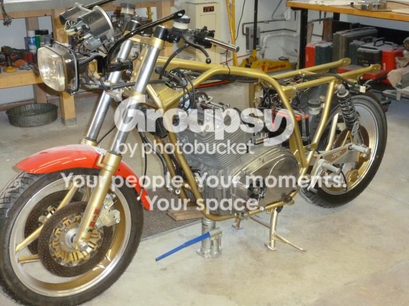
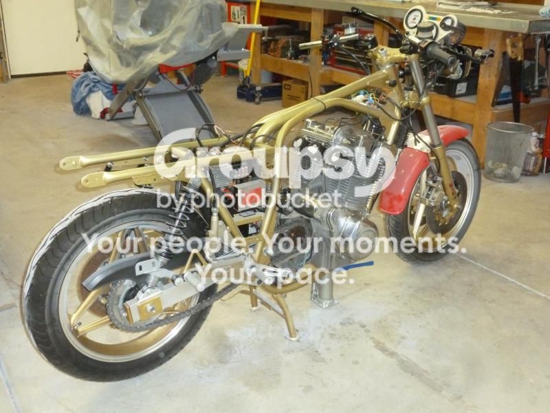
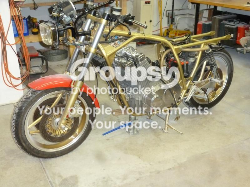
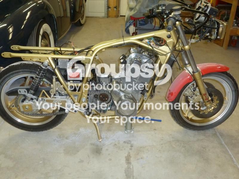
Bare Naked SFC1000

Scott, stick with it, I've no doubts that you will get there and that you will have a very nice SFC1000 to enjoy for all your work.

Another Laverda back on the road ............. That's got to be a result.
 
Progress report on reassembly:

Engine back in the frame.

P1020185_zps996edf65.jpg


P1020186_zps49c7ba56.jpg


Next stop; everything else.

Where to start?

Electrify him, I suppose?  :D
 
Rockitdoc said:
Where to start?
Electrify him, I suppose?  :D

no, seal the bloody engine up before you do anything else
so start by installing the rest of the engine covers

 
redax5 said:
no, seal the bloody engine up before you do anything else
so start by installing the rest of the engine covers
Check.  But, before the clutch cover goes on I need to insert the ball bearing and the right half of the clutch actuator rod.  If I insert the ball bearing from the right side (clutch actuator) will it fall down into darkness and be lost or is there a channel for it to roll on?  I can't see with my light what's in there and I didn't notice when the case was split).  Don't want to take this sucker apart again anytime soon!

P1020187_zpsa6446120.jpg
 
you insert one steel rod, I always use the rod with no dimples first but as your engine is such a low mileage engine then I doubt your rods will have dimples yet

then you pop the ball bearing in through the same hole in the sprocket, it cannot go anywhere but into position, slap a dab of grease on it first, use EP type of grease for extra performance  :D

last, insert the remaining steel rod also with the same high performance grease  :D


redax5 said:
you insert one steel rod, I always use the rod with no dimples first but as your engine is such a low mileage engine then I doubt your rods will have dimples yet

then you pop the ball bearing in through the same hole in the sprocket, it cannot go anywhere but into position, slap a dab of grease on it first, use EP type of grease for extra performance  :D

last, insert the remaining steel rod also with the same high performance grease  :D

Many thanks Red.  When this project is over, I owe you, and all the others who've helped, at least a couple of pints
 
Lots of progress today:

1.  Wire loom almost hooked up (the home for one wire (black/white) the diagram says goes to flasher unit, but my flasher unit only has two poles while diagram says it should have three.  Getting hold of Wolfgang to get me another flasher unit with three poles.  Also can't find a home for a green/gray wire with female bullet connector up by the coils.  Diagram says it goes to the instruments (I think).  Any help with this one appreciated.

2.  Hooked up spark plugs and watched while they sparked as the engine turned over using the little button on the right switch cluster.  Wheew!  Progress.  :D

3.  Turned on key and I get:
headlight/hi low
taillight
horns
starter
plug sparks

4.  Still to be worked out:

turn signals no workie but I get the right orange arrow on the dash to light up when either the left or right turn signal switch is activated.

neutral light doesn't seem to work, yet.

dash lights do not come on with headlights

No hydraulic fluid in the system so I can't check the brake lights, yet.


BTW, my Telefix clip-ons do not ground to the handlebars.  That means I have to run a ground wire for the horns to work.  I by-passed the handlebars with alligator clips and got the horns to work.

Onward...................................................... :D


Green/Grey is the trigger wire for the electronic tacho on the RGS, not required on your machine. Flasher relay is a flasher relay, I use two wire solid state units.

  Keith
 
laverdakeith said:
Flasher relay is a flasher relay, I use two wire solid state units.

  Keith
Thanks, Keith.  I'll tie off the green/gray wire. 
What's the purpose of the black/white wire?  Manual shows it going to 'P' on flasher at one end and the same apparatus as the green/gray wire on the other end.  Something to do with the electronic tach?
 
I'm guessing it's the repeater lamp feed for the dash, or the lights on lamp. Dunno without a wiring diagram... always a good point of reference!
 
Rob said:
I'm guessing it's the repeater lamp feed for the dash, or the lights on lamp. Dunno without a wiring diagram... always a good point of reference!

Yeah, wiring diagram is not much help.  It just shows the white/black wire going to an un-named thing a ma jig up near the tach. 
 
anyway useless for you, as you have DMC  instead of the standard 3 Bosch ignition boxes and that wire isn't connected to the DMC I think... at least I think its not because DMC 1 has no tacho output (DMC 2 has, but its not activated afaik.
 
Laverdalothar said:
anyway useless for you, as you have DMC  instead of the standard 3 Bosch ignition boxes and that wire isn't connected to the DMC I think... at least I think its not because DMC 1 has no tacho output (DMC 2 has, but its not activated afaik.

Too true.  To wire up the Witt DMC I followed the instructions on the side of the unit.  Most of the text was still readable.

Do you know a source for the wiring diagram specifically for my bike? That is, an SFC with DMC?  I'm still tracking down some of the items that are not working properly and it might speed up the process.

 
I think there is no such thing as a SFC wiring diagram, especially not with the DMC installed, as that is an aftermarket option. But I'll check my files later today...  ;)
 
Laverdalothar said:
I think there is no such thing as a SFC wiring diagram, especially not with the DMC installed, as that is an aftermarket option. But I'll check my files later today...  ;)
Lothar,
The alternator has two of each of the yellow and blue/white wires (four total + the green/white wire) but only one wire of each (blue/white and yellow) coming out of the voltage regulator.  When I took the bike apart, one of the blue/white and one of the yellow were tied off and not connected to anything.  Should I do that again, or run both yellows and both blue/whites into the one connector coming off the regulator?
 
Looking at the RGS wiring diagrams, and referencing my own bike, there are only 3 wires coming from the alternator...which is what you'd expect for a 3 phase alternator.  You could try checking resistance between the wires to see if those of the same colour are common (which is logical).  Or you could just put it back the way it was and check voltages when you've got the thing running.

Ref your earlier question and now that I've looked at the diagram - the P terminal on the flasher should indeed go to the repeater lamp on the dash
 
Rob said:
Looking at the RGS wiring diagrams, and referencing my own bike, there are only 3 wires coming from the alternator...which is what you'd expect for a 3 phase alternator.  You could try checking resistance between the wires to see if those of the same colour are common (which is logical).  Or you could just put it back the way it was and check voltages when you've got the thing running.
Any reason not to tie the two wires together from the alternator and then connect to the single wire from the regulator?

Rob said:
Ref your earlier question and now that I've looked at the diagram - the P terminal on the flasher should indeed go to the repeater lamp on the dash

What's a 'repeater' lamp?  And, does this lamp exist on the SFC dash?

s
 
Repeater lamp = indicator indicator, if you know what I mean. ie the little light on the dash that flashes at the same rate as your indicators to show they are working.
 
Back
Top