Cam pillar mounting types

Jota Rob

Hero member
Location
England
Hi All
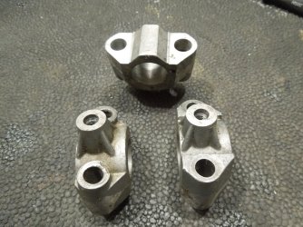
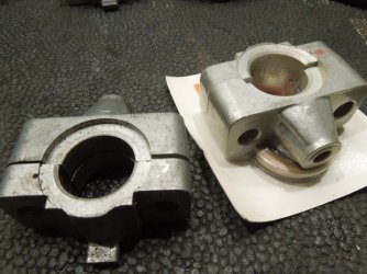
On the triples, how many designs of cam pillar mountings were employed?

I've posted two types.
The earlier type looks like the pillars were free to self centre (once the cam is installed).

The latter employs a shoulder, does this shoulder conform to the shoulder on the billet cam pillars. Ie is the pillar locked in place or is it still free to self Centre? ( I think locked because they are often seen chewed up but I don't have mine to measure)

Was the later system more effective, ie with the cams positively located?

Finally, if you still follow, as its a weak spot for the small area that the pillars pulls down onto the head, should/ could the step also be used to support the pillar, ie some careful milling of the head, to match the pillar step.

Many thanks.
 

Attachments

  • Screenshot_20250206_133528_Gallery.jpg
    Screenshot_20250206_133528_Gallery.jpg
    116.4 KB · Views: 24
  • Screenshot_20250206_133844_eBay.jpg
    Screenshot_20250206_133844_eBay.jpg
    241.3 KB · Views: 24
Hi All
On the triples, how many designs of cam pillar mountings were employed?

I've posted two types.
The earlier type looks like the pillars were free to self centre (once the cam is installed).

The latter employs a shoulder, does this shoulder conform to the shoulder on the billet cam pillars. Ie is the pillar locked in place or is it still free to self Centre? ( I think locked because they are often seen chewed up but I don't have mine to measure)

Was the later system more effective, ie with the cams positively located?

Finally, if you still follow, as its a weak spot for the small area that the pillars pulls down onto the head, should/ could the step also be used to support the pillar, ie some careful milling of the head, to match the pillar step.

Many thanks.
At least 4, Rob.

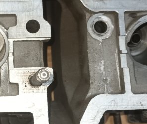
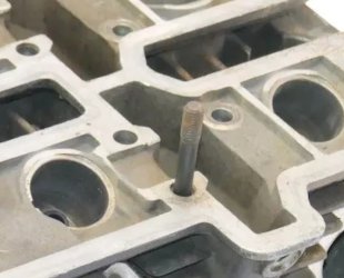
Of the earlier, dowel-located type, there were 2, the later version gaining strength around the stud bores to prevent crumbling.

The later type were positively located by the slot in the head. The ham-fisted amoung us rarely kept an eye out if the bearing blocks engaged correctly while buttoning down the cams, therefore many slots are now mangled, often beyond proper use, ie, valve clearances are a pita to adjust because cam fitment is no longer exactly repetitive. The 180° cams allow positioning in the head without depressing a valve... the cams CAN be fitted by placing all three bearing blocks in their slot and tightening. The mangled slots are caused by the blocks entering at an angle. Early examples of these bearings had a counterbore to accomodate the dowels from the earlier engines, making them an easy retro-fit for the mostly crumbled early type bearings. This counterbore was omitted in later productionn.

The 120° engines had a deeper slot/groove with the bearing having a corresponding deeper spigot. The 120 cams cannot be fitted without having at least one valve pressing on it, the deeper slots and longer spigots allow the bearings to be gradually introduced squarely into the slots when buttoning down. Of these, there were at least 2 different types, the final version having a bronze thrust half-washer incorporated into the top half of the centre bearings. The bronze thrust pieces were supplied in 2 thicknesses with each replacement bearing to allow accurate adjustment of axial play. While the 180° cams were located axially by an inserted crescent in the centre bearing running in a groove in the can journal, the 120 cams had a shoulder each side of the centre bearing. The 120 bearings retained the locating groove for the crescent and had decreased oil supply bores for the tappets, probably taking the higher flow volume of the oil pumps into account.

So, to sum up, the latest bearings were the stongest, but care must be taken to have the cams spin freely when rebuilding the head. Before final torquing, a firm downward tap on the cams next to the bearings with an alloy bar will centre the cams within the bearing if the slots allow too much slop. Not uncommon to find bearings that have been altered at their base, resulting in incorrect heights. A sliver of alloy can also often be found squashed to the base next to the spigot, a result of the bearing slicing off a bit of head when tightened at an angle.

HTH,
piet
180 dowel-type.JPG180 slot-type.JPGJota 120, RGS onwards.JPGFinal centre type SFC1000.JPG
 
Back
Top