Digital MAP/TPS module to be used with Ignitech TCIP4 ignition unit.

Can follow Jouni missive, high degree of technical competencies, initiative also. Hardware to progging, ( coded with what software tool Jouni? )

Flame propagation rate varies with the fuel/air mixture, ie fiddling with ignition retard ( there is no "advance" ) to compensate for less ideal stoichiometric and the modern soup masquerading as fuel. Ideal engine power moment to moment responce, can be achieved by fuel/air regulation or ignition timing ( static comp ratio a given ). If you cannot precisely measure fuel delivery then you revert to MAP, as to combustion chamber requirement, ie instantaneous piston velocity, RPM is a misnomer in electronics, though we use it as a general term, instantaneous velocity is the actual desired input measure to the microprocessor. MAP is a "demand" parameter from the combustion chamber/valve train operation.

Takes some doing sorting the above, Jouni is a capable person by all and any accounts, well done.

One of the parameters that i consider vital for the air cooled Laverda, exhaust gas temperature at the initial header bend. Lean mixtures ( and rich mixtures ) burn at a lower temperature than correct stoichiometric ratio. Lean mixtures do not burn hotter, fallacy, it does however not allow proper piston cooling from incoming fuel load ( overly high ignition retard may solve one issue, only to cause less cooling for the piston crown ) . Over rich will also burn at a lower temperature as stated. There you have a fading techs missive. j
 
...coded with what software tool Jouni? )

...
This question needs to be addressed to Sami.

Generally speaking microcontroller manufacturers today are distributing software development tools for their products often freely downloadable on their websites and/or on their development kits. I would check the webpage of Microchip Technology Inc., the manufacturer of the microcontroller.

I think this would be a good link to start with:

-Jouni
 
Last edited:
The program code is standard C++. I’m using Arduino_IDE software with ATtiny usb programmer to burn the code to microcontrollers flash-memory.
 
Ok, so no one step up from machine code, source file. Old school mnenomics for me, a grin here. Given all my main stream code was in Intel assembler, macro later on. Optimized code at compilation invocation for higher level languages, and simple instruction sets, would be more advanced since 1995, would think.

Many HLL interpreters and compilers in the day then. Forth one of the more unusual ones. Emulators became sort of useful. Sami you must have had a challenge with external data input for the code generation debug/operation. Unless you write perfect code in one go, well done if you do... a smile here.

Used C, then C+ not so much C++ Pascal was a flavor one upon a time, that era. The C compiler ran on S100 8/16 8085 8088 dual procc, CP/M OS, the C compiler authored by a Jewish lad in New York with all sorts of yiddish run time compilation error calls, hard calls to the BIOS being a no no in the day.... old person ramble... like the 60 minute compilation run time in 1985.... all on 8"floppy Yedata drives. Not sure of the value in all this reply, like when we were young listening to grandad talking about old times, how long you listened was a skill learned...j.
Well John 8" floppy drives, you are talking about modern computers. When I started we had 80 column coding sheets that you gave to the punch operator and then later programs were stored on a cassette tape and then 8" floppy by about 1978 to write programs for the Intel 4004.
 
Ah Bruce you old dinosaur... well one up on me, suppose you had an IMSAI binary loader as top of the range....? Have somewhere here in a matchbox, the very same Intel 4004.

Rockwell had an early version uP, more like a box of fleas in it was easily nuked, used in many point of sale machines in the day, every time it nuked we had to load in the OS in hex, on a decimal only keypad with shift to A-F, was about 2k of OS, them volatile memory had crosslink cell issues, and would overwrite previous cells.... and crash again.... wot fun say wot.... j
 
Back to the actual topic. Just in case there is still confusion what the module does, here’s a summary. I’m using it with an earlier v.75 version of Ignitech TCIP4, but it really doesn’t matter which version you have. The later versions, like v.96, have on option to use TP-sensor or MAP-sensor, but not both. So, the module is an upgrade to your existing TCIP4 unit. It reads the voltage from both sensors, and then converts them to digital data, calculates the info and combines it to weighted average (I’m using MAP 40%-TPS 60% ratio). The final output is a steady DC-voltage, which is send to TCIP4 TP-input. With this voltage you can adjust the 3D-advanse map, which takes into account the rpm and TP (calculated engine load and throttle position). And why? You will have a better running engine and better fuel economy.

Anyway, my offer stands. I will make these to order. The price is 30€/module + shipping. I don’t stock the components, so it will take a couple of weeks to finish the product, but then again, I will need the voltage readings from your existing sensors to program them to the module’s memory. After that, the module is coded specifically for your bike’s sensors.

edit: Assembling the module is so laborious and time-consuming that I have to raise the price -> 40 €/module + postage.
 
Last edited:
That is a great offer Cape. I fear such is within the capacity of very few of us on here. I have thought of adding a TPS, mounted separate from the carburettors with a cable splitter as there is no way to fit it directly.
John`s mention of exhaust temp sensor mounted at the first bend was what many racers did here but you don´t see them so much now, A/F sensors are common.
 
Sounds like a great offer indeed, Sami. Have you got a pic of a MAP sensor fitted? Do they just work of a take-off post carb pre-head?

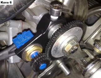
And your gear-driven TPS looks tidy. I reckon I could convert my FCR Keihins with a system like that. Might PM you when i get a bit of time later this week.
 
Have you got a pic of a MAP sensor fitted? Do they just work of a take-off post carb pre-head?
MAP sensor is connected to inlet manifold vacuum, that is a pressure tube from the sensor to the carburetor balance tube. You will need a T- shaped tube connector…
 
Some Kehans have TPS as standard; maybe you could adapt that bit.
rottle Position Sensor (TPS)
    • What it does: The TPS is a small sensor mounted to the throttle shaft or cam. It reads exactly how wide the flat-slide is open and sends a voltage signal to the bike’s CDI/ECU. [1, 2]
    • The purpose: This allows the motorcycle's ignition system to dynamically adjust ignition timing based on both engine RPM and throttle position. It optimizes throttle crispness, midrange torque, and top-end power. [1, 2]
    • Where it’s standard: It is standard equipment on almost all modern Keihin FCR-MX carburetors found on factory four-stroke dirt bikes (like the Honda CRF, Yamaha YZ/WR, Suzuki RMZ, and Kawasaki KXF) as well as various sportbikes and ATV
 
My FCRs are made from a chopped up bank of four that came off a GSX-R1100. Problem is that the throttle shaft on the right is directly in line with a and very close to the RH fuel tap. Need to look at simple ways around it (the problem and the tap :cool: ).
 
My FCRs are made from a chopped up bank of four that came off a GSX-R1100. Problem is that the throttle shaft on the right is directly in line with a and very close to the RH fuel tap. Need to look at simple ways around it (the problem and the tap :cool: ).

Moving the tap boss wouldn’t be too hard, before repainting after your get off.
 
Software version 3 rolling out!

A module that reads signals from a MAP sensor and a throttle position sensor (TPS) and processes them via software. The resulting combined signal is then sent to Ignitech TCIP4 ignition unit.

TCIP4 is the best aftermarket ignition unit available on the market, and its features include support for either a MAP sensor or a throttle position sensor. Data from these sensors can be used to adjust the 3D ignition advance curve. This results in improved ignition performance across various RPM ranges and engine loads, optimizes the fuel combustion process, and leads to benefits such as reduced fuel consumption. Unfortunately, the TCIP4 only allows for the use of either a MAP sensor or a throttle position sensor—not both simultaneously.

This digital module is designed to solve this limitation, enabling the use of both a MAP sensor and a throttle position sensor. Based on a programmable ATtiny85 microcontroller, the module offers the following features:

• Signals from the MAP sensor and the throttle position sensor are read independently. The software processes these signals, filters out noise, and calculates a weighted average (e.g., 40% MAP and 60% TPS). The processing and calculation utilize the maximum and minimum signal voltages measured from the sensors. These provide the scales required for adjustment, processed with a precision of one-thousandth (0.1%); the resulting signal sent to the ignition unit is highly accurate and stable.

• The module continuously monitors the sensors for potential faults—starting from the moment the module powers on and throughout normal operation. If a fault is detected, the module enters a fail-safe mode, indicated by an illuminated LED. This does not happen due to a single, isolated signal glitch; the fault must persist for a specific duration—in practice, 20 program cycles. If the fault is resolved, the system returns to normal operation after a corresponding number of cycles. Since the program executes approximately 450 times per second, these checks are extremely fast (60 ms).

• In fail-safe mode, the signal voltage sent to the TCIP4 unit drops to a clean 0 V. The ignition unit reacts to this immediately, reverting the 3D advance curves to the base (default) curve.

• The module’s software also performs self-monitoring; should it freeze for any reason; it will automatically restart after 120 ms.

• The microcontroller features an internal safeguard: if the supply voltage drops below 2.7 V, the system enters fail-safe mode.

• The module’s design accounts for motorcycle electrical system standards, OEM sensor signal levels, and the safety limits of the sensor inputs on the Ignitech TCIP4 ignition unit.

• Before programming the module, the sensors to be used must be calibrated—that is, the maximum and minimum signal voltages are measured. These voltages are converted into a digital format and programmed into the module. The end result is a module programmed specifically for the sensors being used.

If you are skeptical about the module, or don’t need one – well, don’t order one. Otherwise drop me a line!

Cheers,
Sami
 
Back
Top