DMC2 wiring for an SF2

Mshockites

New member
Location
Florida
Hello guys,
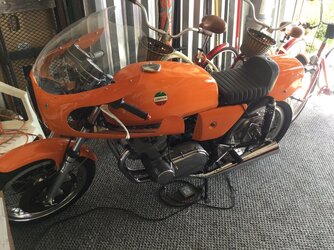
I’m new to the forum but been buying, selling, restoring and collecting vintage bikes for 40 plus years. I’m restoring an SF2 into an SFC clone. Bought the bike 25 years ago and been collecting parts as it languished in the shop ever since. COVID got me motivated and I’m in the homeward stretch but wrestling with a DMC2 ignition as I have no German skills. I’ve muddled through the mechanical end but really struggling with the wiring. Let’s talk about the 4 leads coming off the box (red, white, black and gray). I found a diagram somewhere on line that shows the red going to both coils but I can’t see where it then terminates? I’m assuming black is a ground? White and gray to each coil but what side? Further, am I to remove the existing coil wires (used a dual points stock ignition) when I wire the new system or add to the already wired coils? Any help, advice or direction would be tremendous. I don’t like the option of throwing the old points back in and timing it that way for the initial fire up. Thanks…..Mark
 
Full instructions (in English!) are in the library
https://laverdaforum.com/xf/resources/6/download

You'll see that the usual approach is to retain the switched ignition feed to the coils and use that to supply 12v to the DMC box via the red wire.
Black is indeed ground. A good solid connection is required. If in any doubt, connect directly to the battery negative terminal.
Grey and white wires go to the 'earthy' or negative side of the coils - left and right cylinder respectively. You've already got 12v connected to the other side of the coils.
 
Last edited:
Hello guys,
I’m new to the forum but been buying, selling, restoring and collecting vintage bikes for 40 plus years. I’m restoring an SF2 into an SFC clone. Bought the bike 25 years ago and been collecting parts as it languished in the shop ever since. COVID got me motivated and I’m in the homeward stretch but wrestling with a DMC2 ignition as I have no German skills. I’ve muddled through the mechanical end but really struggling with the wiring. Let’s talk about the 4 leads coming off the box (red, white, black and gray). I found a diagram somewhere on line that shows the red going to both coils but I can’t see where it then terminates? I’m assuming black is a ground? White and gray to each coil but what side? Further, am I to remove the existing coil wires (used a dual points stock ignition) when I wire the new system or add to the already wired coils? Any help, advice or direction would be tremendous. I don’t like the option of throwing the old points back in and timing it that way for the initial fire up. Thanks…..Mark
Please do not transform a very good road bike into another SFC clone. You'll just make a bad sports clone out of a good road bike. Or go the whole hog, lighten the crank, phase it at 270°, get a close ration gearbox, some high compression pistons, lighter valves and you'll have a classic sports bike.

(you could even leave the points on it, you're having problems with the electronic ignition before even having fitted it)

Paul
 
Please do not transform a very good road bike into another SFC clone. You'll just make a bad sports clone out of a good road bike. Or go the whole hog, lighten the crank, phase it at 270°, get a close ration gearbox, some high compression pistons, lighter valves and you'll have a classic sports bike.

(you could even leave the points on it, you're having problems with the electronic ignition before even having fitted it)

Paul
Or do all the motor work, uprate the suspension and brakes front and rear and keep the appearance the same. That would make an even better road bike! But I can certainly understand the appeal of an SFC, they are beautiful.
 
Or do all the motor work, uprate the suspension and brakes front and rear and keep the appearance the same. That would make an even better road bike! But I can certainly understand the appeal of an SFC, they are beautiful.
I bought the bike as a roller some 25 years ago missing a lot. It was sitting in an exposed shed for some 10 years before I acquired it. It did come with a box of parts that included some switch gear, a speedo nuts and bolts and the like. I’m a purist with the rest of my bikes so my preference would have been to take it back to original but too much was missing. Over the years, I found many SFC goodies like front fairing and mounts, tank, seat with rear stub fender, wheels, side panels, wind screen, rear sets, Ceriani 38 fork legs and front Brembo discs and calipers. I had the correct clip ons on the shelf along with a Grimeca front master cylinder and Tomaselli clutch lever so I’m starting to pull it all together Now. The motor was seized but surprisingly quite clean inside When I tore into it last year. Had the barrels resleeved with standard size Ross pistons, new valves, guides, springs, cam chain, primary chain, clutch along with the usual new parts and going back together nicely. It’ll just be a stock SF2 motor with some SFC eye candy. I’m too old to ride any distance in a lay down position. Around the block a time or two to say it ran and I rode it. I’m at the point I can barely do an hour on any of my upright seated bikes. I do enjoy the challenge of the restoration process.
 
Full instructions (in English!) are in the library
https://laverdaforum.com/xf/resources/6/download

You'll see that the usual approach is to retain the switched ignition feed to the coils and use that to supply 12v to the DMC box via the red wire.
Black is indeed ground. A good solid connection is required. If in any doubt, connect directly to the battery negative terminal.
Grey and white wires go to the 'earthy' or negative side of the coils - left and right cylinder respectively. You've already got 12v connected to the other side of the coils.
Rob,
I’ve installed a dozen Pazon ignitions on my Brit bikes with no problems. The wiring is relatively simple. However, I’m really wrestling with the 2 banks of 12 in and out connectors on this SF2. I’ve blown up and colored a wiring schematic to trace all the leads trying to make sure it’s wired correctly to factory specs to begin with. Not knowing what previous owners may have done. The original harnesses are in nice condition and not boogered up. Reading your instructions 50 times over, I’m not sure how to proceed. Here‘s where I am: I’m using the hot switched red feed that went to the points to power the new box. Ground is self explanatory. Grey wire to the negative side of the coil firing the left cylinder and white to the corresponding negative side of the other coil. Now, do I remove all the existing wires to both coils? The + side of the coils are connected to each other and to the red wire that fed the points which I’m using for power which I think should all stay. I’m sure I’m making this harder than it should be but if you could help me through it, I’d be forever in your debt……Mark
 
Hi Mark

You're in danger of overthinking this!
You definitely need a 12v live feed to both HT coils when the ignition is switched on. The white and grey wires to the DMC are switching off the current through the coils to generate the spark. So carry on as you thought. Don't worry about fact that the DMC box also needs a live feed with ignition on... all that does is power the internal electronics. Typically I use the 12v feed to the coils to also power the DMC box.

Hope that helps!
 
Hey Rob,
Thanks for your help. I was over thinking the issue. I was frustrated as I was certain I had it wired correctly and no spark. Went back over all the wiring to make sure nothing was crossed or mis wired. Turns out the 3 pin connector to the DMC was faulty. The male pins weren’t going deep enough into the female plug so no contact. Once I swapped that out I had great spark. Thanks again for the words of encouragement and your help. All the best……Mark
 

Attachments

  • F36D5772-1EC4-4037-A277-5D433775AB74.jpeg
    F36D5772-1EC4-4037-A277-5D433775AB74.jpeg
    227.3 KB · Views: 12
Glad you got sorted. The AMP Superseal connector does need the pins to be carefully crimped on to the conductors with the seals, and the pins will only click home in one orientation. It can need the crimped pin and wire assembly to be given a push with a blunt item against the seal to overcome its stiction to help fully seat the pin with a 'click'. Superseal crimp.jpg
 
Back
Top