
You are using an out of date browser. It may not display this or other websites correctly.
You should upgrade or use an alternative browser.
You should upgrade or use an alternative browser.
Dodgy 750 front/rear brake light
- Thread starter TeddyG
- Start date


Tippie
Hero member
- Location
- Dr?bak, Norway
The globe is earthed permanently. The switch circuit gives power to the brake light globe filament. If that circuit is earthed before the filament it will short out and blow the fuse (hopefully).It's a loop with a switch.
Problem is either switch or an unwanted earth.???
Paul

TeddyG
Hero member
- Location
- Portland Oregon
Thank you all, and yes I know it's difficult to diagnose this remotely w/o enough info. The wires that snake behind the fuse box are very short, so it's hard to get a decent photo to show exactly where the wires are going. I will post a diagram showing this later today. My thoughts are that it's a wiring issue w/ one of the switch wires that is causing the bright light circuit to be permanently on. I'll disconnect the wires and test them for continuity. I only know that the odds of both switches crapping out together are remote, so it must be the wiring. If I can find a replacement for the front M10x1 switch I'll install that since the present 50 yr old is probably due for replacement.
TeddyG
Hero member
- Location
- Portland Oregon
Disclaimer- electricity is obviously not my strong suit, so bear w/ me.
With my meter set to 200 resistance , "1" is displayed at the left side of the screen. With the meter leads connected to the hydraulic front switch, once the front brake lever is engaged, the screen displays @ 1-2 on the right portion of screen. It does the same thing to the mechanical rear switch connected the same way and pulling out the spring plunger. Which leads me to believe the switches are both good, and that the problem w/ the permanent bright tail light bulb must be the wiring to the bulb itself. I know there's 2 wires and a grounding wire attached to the frame fender mount.
With my meter set to 200 resistance , "1" is displayed at the left side of the screen. With the meter leads connected to the hydraulic front switch, once the front brake lever is engaged, the screen displays @ 1-2 on the right portion of screen. It does the same thing to the mechanical rear switch connected the same way and pulling out the spring plunger. Which leads me to believe the switches are both good, and that the problem w/ the permanent bright tail light bulb must be the wiring to the bulb itself. I know there's 2 wires and a grounding wire attached to the frame fender mount.
Tippie
Hero member
- Location
- Dr?bak, Norway
Keep at it and you will learn, it can take a while to get your head around but once you do you are an expert. Just be happy that you aren't dealing with something like Paul with his Kawasaki headlight. It is easier to do simple fault tracing on a 12V system with one of those little screwdrivers with a light inside and a wire to an alligator clip.
TeddyG
Hero member
- Location
- Portland Oregon
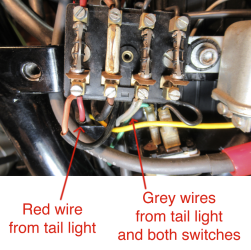
Here's a pic showing how the wires from the tail light and both switches attach to the fuse block. The 5 grey wires from the 2 switches and tail light all converge into the 2 grey wires attached to the 3rd fuse terminal.The one red wire from the tail light attaches to the first fuse terminal.
This is how the bike came to me and I haven't changed anything, and the stop light was acting fine until now. The wires are firmly attached and there's no other loose wires near the fuse block.
With new brake light bulbs, only the brighter and larger filament is glowing, with or without both or individual light switches connected. There's no change to the bulb with either switch connected and activated.
My next step is to buy a new front hydraulic switch and hope it works
This is how the bike came to me and I haven't changed anything, and the stop light was acting fine until now. The wires are firmly attached and there's no other loose wires near the fuse block.
With new brake light bulbs, only the brighter and larger filament is glowing, with or without both or individual light switches connected. There's no change to the bulb with either switch connected and activated.
My next step is to buy a new front hydraulic switch and hope it works
Attachments
Just a couple of random thoughts:
- the two grey wires look like figure-8 speaker wire. Which would be non-standard. Why is it there?
- the rear light globes are dual filament, is there any possibility of them being installed incorrectly, so the brake light filament is energised as if it was the tail light? I know the side pins are staggered to prevent this from happening.
Cheers,
bazzee
- the two grey wires look like figure-8 speaker wire. Which would be non-standard. Why is it there?
- the rear light globes are dual filament, is there any possibility of them being installed incorrectly, so the brake light filament is energised as if it was the tail light? I know the side pins are staggered to prevent this from happening.
Cheers,
bazzee

Dellortoman
Hero member
- Location
- Tasmania, Australia
Why buy a new brake light switch? You've already eliminated that as being the problem in two different ways. You removed the switches from the circuit ant the problem remained, and you tested both switches with your meter and they work. You concluded that the problem was with the wiring and not the switches. I think that conclusion was correct.
The red wire that you previously identified as going to the rear switch, you now say (in your latest photo) goes to the tail light. So which is it, light or switch? It's important to know where wires go when you're trying to diagnose electrical issues.
You're getting a 12V feed to the brake light when you switch the ignition on, so there's a permanent connection between those two that's bypassing both brake light switches.
You say it was working before, and nothing has changed. Are you really sure about that? Was there a loose wire at the fuse box that you re-connected, and perhaps put in the wrong spot?
I think at this stage, perhaps your best way to proceed is to remove one fuse at a time to see if the light goes out. That may give you a clue as to which circuit is feeding power to the brake light.
How original is the wiring? If the bike has been messed about with then the wiring diagram may not be of any use. But the fuse box appears to be original, so hopefully the wiring diagram is relevant.
The red wire that you previously identified as going to the rear switch, you now say (in your latest photo) goes to the tail light. So which is it, light or switch? It's important to know where wires go when you're trying to diagnose electrical issues.
You're getting a 12V feed to the brake light when you switch the ignition on, so there's a permanent connection between those two that's bypassing both brake light switches.
You say it was working before, and nothing has changed. Are you really sure about that? Was there a loose wire at the fuse box that you re-connected, and perhaps put in the wrong spot?
I think at this stage, perhaps your best way to proceed is to remove one fuse at a time to see if the light goes out. That may give you a clue as to which circuit is feeding power to the brake light.
How original is the wiring? If the bike has been messed about with then the wiring diagram may not be of any use. But the fuse box appears to be original, so hopefully the wiring diagram is relevant.
TeddyG
Hero member
- Location
- Portland Oregon
Thank you both- the grey wires are the original wires within the brake light and both brake switches. I,m using brand new bulbs that can only go in one way, and only the brightest/ largest filament is lit.
I haven,t touched any of the wires to the fuse box nor added any. The wires are all original and in original sheathing. As noted before, the red wire attached to the fuse box is from the brake light. The brake light has one red and one grey wire and the wires from the front and rear switches are all grey.
When the first 2 fuses are removed that contain these wires, the bulb of course turns off.
I was contemplating a new front switch since I,m not sure that my continuity test is correct and I,ve run out of ideas.
I haven,t touched any of the wires to the fuse box nor added any. The wires are all original and in original sheathing. As noted before, the red wire attached to the fuse box is from the brake light. The brake light has one red and one grey wire and the wires from the front and rear switches are all grey.
When the first 2 fuses are removed that contain these wires, the bulb of course turns off.
I was contemplating a new front switch since I,m not sure that my continuity test is correct and I,ve run out of ideas.
Last edited:
Tippie
Hero member
- Location
- Dr?bak, Norway
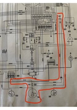
You do not need to continuity test either switch with a multi meter, just remove the wires. If you remove those wires from the switches and the brake light filament is still lit up, you just have to find the source of that power. The grey wires to the switches are very easy to trace along the loom, on my SF2 they do not even enter the harness but are just cable tied along with it, easy to see if they are contacting some power source. The tail light itself is part of the parking light circuit that comes on with the lights in either park or headlight mode, they have nothing whatsoever to do with the brake light circuit. Your terminology is misleading when you label the grey wires "to both switches and tail light", what you mean is "to rear lamp assembly". I have taken a pic from my manual and attach it. There could not be a simpler circuit, don't over think it.
Attachments
Dellortoman
Hero member
- Location
- Tasmania, Australia
I've been trying to find a wiring diagram for a 750 that has 4 fuses. There was nothing in the Library section. I see that Lee has one so they must exist! I found one online that I've now uploaded to the library https://laverdaforum.com/resources/sf3-wiring-diagram.144/history
It's not a particularly good copy, and it's in French. There may be better ones out there if anybody is keen to look.
Lee (Tippie), is there any chance of you uploading an image of your wiring diagram to the Library?
It's a bit hard to follow the wires on a monochrome diagram, but I think your fuses are from left to right: Park light; Lights/horn; Brake light; Indicators.
12V power for the brake light comes in at the top of fuse 3 and goes to the two switches in parallel (the two grey wires).
There would be a wire from the other side of each stop switch that goes to the brake light, and then to ground via the lamp filament. In reality, the two switch wires probably join together somewhere in the wiring harness and a single wire goes to the light. It must be somewhere in this bit of the wiring system that you're getting a spurious feed from a live wire. It's the only part of the brake light circuit that bypasses both brake switches. Follow the wires "downstream" of the brake light switches until you find something that doesn't look right. Maybe some insulation rubbed through against another spade connector or something.
It's not a particularly good copy, and it's in French. There may be better ones out there if anybody is keen to look.
Lee (Tippie), is there any chance of you uploading an image of your wiring diagram to the Library?
It's a bit hard to follow the wires on a monochrome diagram, but I think your fuses are from left to right: Park light; Lights/horn; Brake light; Indicators.
12V power for the brake light comes in at the top of fuse 3 and goes to the two switches in parallel (the two grey wires).
There would be a wire from the other side of each stop switch that goes to the brake light, and then to ground via the lamp filament. In reality, the two switch wires probably join together somewhere in the wiring harness and a single wire goes to the light. It must be somewhere in this bit of the wiring system that you're getting a spurious feed from a live wire. It's the only part of the brake light circuit that bypasses both brake switches. Follow the wires "downstream" of the brake light switches until you find something that doesn't look right. Maybe some insulation rubbed through against another spade connector or something.
Dellortoman
Hero member
- Location
- Tasmania, Australia
Just as an aside, the ignition system appears to be un-fused according to the French wiring diagram. You can follow various coloured wires from the battery, via connectors to the ignition and kill switches, then to the coils and points without ever going through a fuse! The starter relay is likewise un-fused, so you should be able to pull all fuses and still start the bike. Is that really the case? (I don't have a 750 so I'm unable to try it).
It seems a bit unlikely to me so I'm beginning to have some doubts about the Froggy wiring diagram.
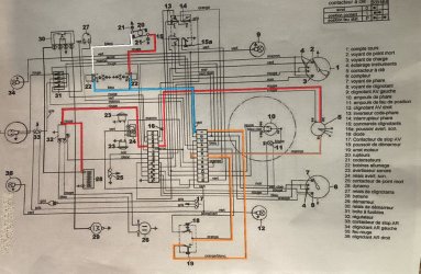
It seems a bit unlikely to me so I'm beginning to have some doubts about the Froggy wiring diagram.
Last edited:
I don't remember seing a 750 with 4 functional fuses.I've been trying to find a wiring diagram for a 750 that has 4 fuses. There was nothing in the Library section. I see that Lee has one so they must exist! I found one online that I've now uploaded to the library https://laverdaforum.com/resources/sf3-wiring-diagram.144/history
It's not a particularly good copy, and it's in French. There may be better ones out there if anybody is keen to look.
Lee (Tippie), is there any chance of you uploading an image of your wiring diagram to the Library?
It's a bit hard to follow the wires on a monochrome diagram, but I think your fuses are from left to right: Park light; Lights/horn; Brake light; Indicators.
12V power for the brake light comes in at the top of fuse 3 and goes to the two switches in parallel (the two grey wires).
There would be a wire from the other side of each stop switch that goes to the brake light, and then to ground via the lamp filament. In reality, the two switch wires probably join together somewhere in the wiring harness and a single wire goes to the light. It must be somewhere in this bit of the wiring system that you're getting a spurious feed from a live wire. It's the only part of the brake light circuit that bypasses both brake switches. Follow the wires "downstream" of the brake light switches until you find something that doesn't look right. Maybe some insulation rubbed through against another spade connector or something.
Paul
Tippie
Hero member
- Location
- Dr?bak, Norway
My SF2 had the four fuse box and they were all used. The wiring diagram is as far as I can recall exactly as my bike came.
I have uploaded phone scans of the diagram and the text pages to the library.
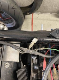
Attached is a pic of the junction of front and rear brake light circuits, a single wire goes from here to the tail light assembly.
I have uploaded phone scans of the diagram and the text pages to the library.
Attached is a pic of the junction of front and rear brake light circuits, a single wire goes from here to the tail light assembly.
Attachments
Tippie
Hero member
- Location
- Dr?bak, Norway
The main fuse before the ignition switch will blow and stop the bike, from experience. It isn't easy to trace through that jumble. I have reduced the wires and passes through the terminal blocks heaps, I have now just one terminal block with a few unused in it. The brake light circuit is still as it came.Just as an aside, the ignition system appears to be un-fused according to the French wiring diagram. You can follow various coloured wires from the battery, via connectors to the ignition and kill switches, then to the coils and points without ever going through a fuse! The starter relay is likewise un-fused, so you should be able to pull all fuses and still start the bike. Is that really the case? (I don't have a 750 so I'm unable to try it).
Dellortoman
Hero member
- Location
- Tasmania, Australia
No main fuse is shown in the diagram I've been looking at. It only shows the 4 in the fuse box.The main fuse before the ignition switch will blow and stop the bike
TeddyG
Hero member
- Location
- Portland Oregon

Dellortoman
Hero member
- Location
- Tasmania, Australia
Ha! I've got an almost identical diagram on a scrap of paper next to my keyboard. Only difference is that I used a black pen for those grey wires.
Tippie
Hero member
- Location
- Dr?bak, Norway
Yes, very simple. Something is providing power to the brake light filament via one of those grey wires with the connector. Disconnect both switches when you are trying to find it.Thank you all again- A friend more experienced w electrics is stopping by and I will pass on all your info and let you know when the problem is solved. In the meantime, here's a diagram of the wiring connected to the fuse block

MarnixSFC
Hero member
My SF2 did when new, now only 2 fuses left..I don't remember seing a 750 with 4 functional fuses.
Paul
Marnix