Earthing question

harpmeister

Full member
Location
UK
When rewiring a circuit on the bike is it best to keep the earth wire the same as the rest of the circuit, for example 1.5mm for the horn and headlight and 2.5mm for the dynamo, regulator etc or is there any benefit in just using say 3mm rated at 33amp
 
Some earthing wires will connect multiple switched feeds to earth, so using bigger wire is actually required sometimes, depending on the circuit and what the loads are. But don't go silly, if you use wire that is too big to comfortably terminate in a connector then it only creates more problems.
 
Andy said:
Some earthing wires will connect multiple switched feeds to earth, so using bigger wire is actually required sometimes, depending on the circuit and what the loads are. But don't go silly, if you use wire that is too big to comfortably terminate in a connector then it only creates more problems.
Very valid point... boy trust me have seen some absolute disasters in my day and those good ugly el cheapo crimp connectors.

You gotta think of the load on the circuit and what it will be carrying then figure out from there.. Don't overkill it on the size.. as whilst you may not think it there can be negative affects from oversizing your wiring. 

Basic rule of thumb I follow

The 20 AWG or 0.5 mm wire is rated at 11 amps and is good for reducing the bulk of a wiring loom eg: around the bars and switches.( except handle grip heaters if your that way inclined ) However it should ideally only be used with smaller type connectors, 2.8 bullets and spade types as it is too small for garden variety standard type bullet & 6.3 mm spades terminals. But it does make for a neat job in areas where space is at a premium, in particular  in the headlight area where on earlier triples it is well crimped.

14-16 AWG circa 1.0 mm is rated at 16 amps and is a good general circuits around  the bike. You can find it in heaps of either plain or colours with traces and will strip with the right tools and crimp also nicely with the red type crimp connectors. I prefer to use high quality heat shrink crimp connectors.. You need the proper crimp tool for these as it is different to the standard crimper.

12 AWG circa your 2.0 mm is rated at 25 amps, I use this for all the main feeds and earth circuits. You don't get the same range of colours but you can get all the basic's and some traces... I found some real nice Orange so tend to use that instead of Red where can on a Lav.. yeh I hear ya but well that's just me.  I like to use for  the alternator wires and such. Works very nicely with the blue connectors or you can if you use it in double the yellow type.

Don't over think your wiring however just make sure you use high quality components and tools and you should be OK.


Not to step on Bretts toes, but I see he's offline...
The red blue or yellow colours of the insulation on the crimp connectors denote size, although only with the reputable brands. The cheap sets from jaycar etc dont seem to have many standards at all. The heat shrinkable ones have heat shrink insulation pre-installed on the crimp that you can shrink afterwards, although some varieties require a different crimp tool. I personally prefer non insulated crimps, because I think they crimp down better (another tool again) then put heat shrink tube on later if required.
 
Piranha Brother 2 said:
Scuse my ignorance, but what do you mean 'red, blue, yellow' crimp connectors, Brett? And shrink type crimp connectors?

Guessing they are those el cheapo connectors that are simply squashed onto the cable.  Quite OK (for a while at least) in a dry, vibe-free environment such as under a car dashboard, but totally out of place on a motorcycle, regardless of application!  These are the main causes for electrical failures that find their way into the OCT workshop.

Proper crimp connectors (one pair of prongs holding the conductor, the other gripping the cable sheath) with either a plastic sheath or heat-shrink tubing to absorb vibes and keep out moisture has proved to be the most durable and reliable method on bikes.  For chassis wiring, I have turned to AMP type connectors, available in many sizes and configurations, and well up to the job in most applications.  They are physically a bit big to cram a bundle of them inside a headlamp shell, so in there, I use the small block and bullet connectors that are almost universally found on jap bikes.  Cheap, readily available and reliable.

Seen too many soldered joints that have either rotted away or simply broken off to develop any sympathy for them.

piet
 
sfcpiet said:
Guessing they are those el cheapo connectors that are simply squashed onto the cable. 

Seen too many soldered joints that have either rotted away or simply broken off to develop any sympathy for them.

piet
Yep they were wot was referring to when suggesting the ones not to use...
however the hi end ones are also colour coded for sizing which I use are
http://www.superiorterminals.com.au/Heat-Shrink-Crimp-Terminals.htm

Correct soldered joints not only introduce brittleness into the wire at the connector but also introduce corrosion due to the flux in the solder... hence the reason that OEM auto suppliers don't use and haven;t used for years. They are all crimp these days..

Back to the topic as we all digressed a tad.. what you need to do is simply calculate the load on the earth circuit and use suitable size wire... I like these type of connectors for multiple earths as makes a real neat job and not too many wires in the one terminal.
http://www.bestboatwire.com/3-way-wire-splice-butt-connector-w-adhesive-heat-shrink-16-14-awg
 
Back to the topic as we all digressed a tad.. what you need to do is simply calculate the load on the earth circuit and use suitable size wire

Agreed but just curious as to whether there is a benefit to using a slightly larger wire
 
Larger wire provides reduced resistance and less volt drop.  This is of no benefit for the return path. You want to minimise volt drop at the load, not after it
 
Rob said:
Larger wire provides reduced resistance and less volt drop.  This is of no benefit for the return path. You want to minimise volt drop at the load, not after it

Except the earth wire is not the return path. Electrons run to the positive.
 
Rob said:
Larger wire provides reduced resistance and less volt drop.  This is of no benefit for the return path. You want to minimise volt drop at the load, not after it

I beg to differ Rob.

It doesn't matter where the volts are dropped, the effect is just the same - fewer volts for what you actually want them for.

So, for a simple path: Battery to lamp, across the lamp, lamp back to battery, you could have voltage drops of:

Supply  Lamp  Return
  1V        10V      1V
  0V        11V      1V
  1V        11V      0V

The former and the latter both give the same 11V across the lamp.

You need to ensure that there is as little resistance as sensible on the whole path, whether supply or return.

Unless you can show me differently?

--
Dick
 
Rob surely with the frame being part of the return path the difference between earth wiring of slightly different gauges would make very little difference.

It was just idle curiosity, something that came into my head that I couldn't work out.
 
Voltage drop happens over an entire circuit, from battery to the load and back to the battery, wherever you make the electrons travel on any particular circuit. Over the short lengths on a bike the actual value of volt drop caused by cable losses is negligible, maybe 1 volt at most, as long as you use a wire size capable of carrying the current running through it. (connections are another story...)
I have seen overloaded wiring melted within a loom, when the plastic insulation has softened and suddenly all the wires were holding hands... However that was a "too much current" issue, nothing to do with volt drop.

Wiring current ratings are variable depending on installation, so don't take the advertised rating as gospel. If a wire rating is advertised it is likely to be its maximum under perfect circumstances, usually relating to the ability of the insulation to manage the heat which is naturally generated in the copper while current is flowing. Most plastic insulation will stand surprising temperatures and are often rated at 50 - 85?C, enough to burn you, but long before it gets that hot the plastic has softened enough that the slightest pressure will damage it.
So to prevent overheating always use a bigger wire than you need when your wiring is in conditions where it is likely to get hotter, without the ability to loose that heat, like inside a loom or near the motor. Also when it is subject to pressure from cable ties or movement.

Sooooo.... back to the original question...
There is no benefit to using a bigger earth wire than you need, from each accessory, so long as you've allowed for all the current likely to go through that wire, plus a bit.
 
Goodness, I didn't know we had such expertise at our disposal! 

Joe - you didn't mention that you were using the frame as part of your earthing arrangement. Lots of steel vs a bit of copper...I'll let you do the resistivity calcs - don't forget the parallel paths!!  :D

Davo - thanks!  (notworthy)

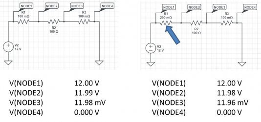
Dick - try this -
 

Attachments

  • unequal resistance - CircuitLab analysis.jpg
    unequal resistance - CircuitLab analysis.jpg
    71.9 KB · Views: 19
Rob. I'm not sure what you are trying to illustrate with your diagram, but the guys are correct. Voltage drop (resistance) in the earth path is just as detrimental as if it were in the supply path. It's still going to reduce the current flowing in the circuit. It also reduces the voltage across the device you're trying to power. 

Yes, with a good supply path you'll have 12V at the load, but that's not the end of the story. If the earth path has a high resistance you'll have a higher than zero volts on the downstream side of your load, as is clearly shown in that diagram you posted. Let's say 1V drop in the earth path for argument's sake. The voltage across the load is then 12 - I = 11V.

If a device is earthed direct to the frame or engine (eg. starter motor), you can't get much better than that on a motorcycle. While the steel of the frame has a lower conductivity than copper. The massive cross-sectional area of the frame tubes in comparison to a copper wire more than makes up for it.

Cheers,
Cam
 
Piranha Brother 2 said:
Scuse my ignorance, but what do you mean 'red, blue, yellow' crimp connectors, Brett? And shrink type crimp connectors?
Chalk and cheese really,
El cheapo connector this time in blue...... real pro job here not and owner wonders why he has electrical issues... joints like this please.
normal_IMG_2568_28229.JPG


Heat shrink crimp connector blue type which indicates correct size for wire.....neater, crimped correctly and water proof.
normal_IMG_2569_28229.JPG
 
Rob: wot Cam said!

:)

--
Dick

PS I like the logical proof reductio ad absurdum: in this case, imagine the 'return path' resistance increasing from the 100 milliOhms in your diagram to say 100 Ohms, or 1,000 Ohms, or the absurd 1,000,000,000 Ohms, then the voltage drop across R2 would be microvolts...
 
Back
Top