I thought I would share some of my recent experiences with Laverda charging, regulator rectifier and voltage.
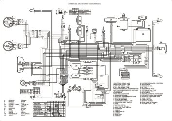
Background: Years ago, I started using Lithium battery. At that point I also modified some wiring. This is ancient history to you all, but to reiterate. What Laverda factory designed, was that the generator 3rd phase went from generator to light switch and from there to regulator. When the headlight is on, the two wires marked as VR and VB are connected, and so is the the3rd phase. When the headlight is off, there is no connection and 3rd phase is not in use. The reason for this kind of wiring is probably to prevent over-charging issues, and as such, it is basically OK. But there are couple of issues. First one is that the wiring is unnecessarily long. The second issue is that if the connectors get worn, there is a risk of 3rd phase shorting to handlebar. That wouldn't be good. Thirdly, if the light switch is turned on and off repeatedly, it will always generate voltage spikes, which are potentially harmful to both regulator and generator. Anyway, Laverda must have calculated that the system will hold, regardless. That may be the case, at least with lead acid battery and traditional shunt regulator. So, I modified the wiring, removing the VR/VB connection and run the wiring through a relay (which was activated by the light switch) directly to the regulator. This fixed the risk of phase shorting to handlebar issue. The wiring was also shorter. Otherwise, wiring is basically the same as original. And it worked with shunt regulator without issues.
Couple of years ago I swapped to a Shindengen FH020AA Mosfet regulator. Mosfet is a great regulator, it keeps the voltage steady at 14,3V or so. But then came the trouble. The voltage started to be unstable, and I thought that Mosfet must have components that are prone to voltage spikes and for that, it failed to operate. I bought a new one and to prevent it from failing, I removed the relay from generator 3rd phase wiring. Same result! Now I was confused, what was going on? I checked every wire, connectors, generator coils, measured everything with multimeter, basically everything I could think of. I swapped back to lead acid battery, no help. I calculated the electricity consumption (I have LED lights), and it turned out that the wattage with stock bulbs is around 96W and with LEDs around 33W. The difference is quite significant. This must be it! I added daytime running lights to the same circuit to get closer to the original consumption. No help! Whaaaaat? And the last thing I checked was the regulator ground connection. I’ve always grounded only to the bike’s frame, but it must have been insufficient. Now I have the regulator ground wire attached to the battery main switch and from there to the battery negative terminal. All good, steady voltage again. So, a simple fault that was a PITA to find...
-Sami