Help - electrical problem

TStanb

Full member
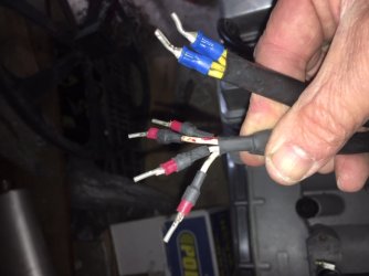
Having collected my Jota engine from the menders, I was dismayed to see that the 1-6 markings in paint* on the six wire terminals coming out the general generator area were missing...'must've come near some solvent or cleaner.
So now I've no idea where these 6 wires are supposed to go.
Does anyone know how I can find out? - don't really want to dismantle the entire RHS of the motor.
Thanks

*will use sticky labels next time
 
Should be easy enough to figure out by looking at the wiring diagram for your model. What year is it? Six wires suggests BTZ ignition. If so they all end up being terminated on to the connector strip below the front of the seat/rear of the tank - colour matches colour across it.  Or are you suggesting all 6 wires are the same colour??!

 
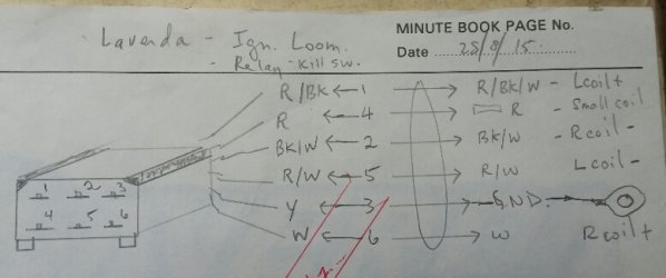
Here is my wiring diagram when I was  using the BTZ CDI ignition on the 3CL.
These are the six wires from the engine to the terminal strip under the seat and on to the Bosch ign.
 

Attachments

  • 2019-04-27 12.30.58.jpg
    2019-04-27 12.30.58.jpg
    166.8 KB · Views: 59
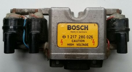
Pardon my French, err, German. I meant to write MHKZ.
The Bosch 1 217 280 036 to be exact.
 

Attachments

  • CDI.jpg
    CDI.jpg
    232.6 KB · Views: 21
The hight tension (red wire) connection from the alternator is not to be mucked around with.  Fit it to the wrong terminal, instant karma... would be wise to sort your aftermarket options beforehand. :D

The others are ground and the 4 wires for the pick-ups.

Generally referred to as HKZ, Hochspannungs Kondensator Z?ndung.  High tension capacitor ignition, or CDI for short.  Basically a magneto, hence the "M".

piet
 
Yes, the red wire comes from the small coil    on the stator which generates about 200VAC to provide the charging voltage for the Primary on the spark coils.
The other 4 wires are the two timing trigger coils for CDI discharge. On my 3CL there was a relay switched by the r.h. kill switch which shorted the trigger coils to kill the engine. Crude but simple and effective.
 
Just trying to understand what your problem is.  You have already identified all the wires from the ignition system. Are you trying to match those up with the wires that come out of the right side of the engine?

It's been a while since I had anything to do with a HKZ ignition. Not many of those still working today. But here are the colours of the wires that emanate from the ignition/alternator side of the engine.

Yellow/black - alternator
Yellow - alternator
White - pickup 1
Black/white - pickup 1
Red - pickup 2
Red/white - pickup 2
Red - ignition primary supply

I don't remember which pickup does which cylinder, but I presume the engine wire colours match the HKZ wire colours. Your only issue is not confusing the red pickup wire with the red coil primary.

PS: Do yourself and your bike a favour and upgrade to a modern electronic ignition.
 
NB, it's a Series 2 Jota.

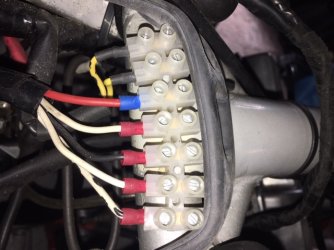
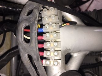
OK see photos attached...someone has done a pretty tidy job at re-wiring but does not appear to have followed the factory colour codes..

coming out of a hole in the general area of the generator are six wires or, to be more accurate, eight. these went into the connector block located on the frame just beneath the rear of the fuel tank...
1 x double yellow wire
1 x double yellow
1 x red with continuous black line
1 x white
1 x white
1 x white with a dotted red line

On the output side of the connector block we have...
1 x yellow with a black dotted line
1 x yellow
1 x thick red (this is OK and has not been disturbed, an orange wire is connected to this on the input side - you can clearly see the yellow paint mark that has rubbed off the other 6 input terminals)
1 x white
1 x black
1 x white
1 x white with black dotted line
 

Attachments

  • jotawiring3.JPG
    jotawiring3.JPG
    111.9 KB · Views: 17
  • jotawiring1.JPG
    jotawiring1.JPG
    108.7 KB · Views: 16
  • jotawiring2.JPG
    jotawiring2.JPG
    77.5 KB · Views: 20
Cannot be a Series 2...

Series 2 would have blue/white, green/white and yellow coming from the ND alternator, all 3 doubled, ie, 6 wires.  3 of these were connected to the bike loom via bullet connectors, the other 3 were tied back, or just flapped around loosely...  Pick-up wiring would come from the LHS of the engine.  MkII triples also did away with the crude connector under the tank.

Doubled yellow points to Mk I triple, 140Watt Bosch BTZ system with 2 large charging coils.  The yellows are connected to the rectifier or regulator.  The pick-up wires were white and white/black for one, white/red and white/red/black for the other.  Pairing can be checked with a multimeter, then just need to get the polarity correct.  This can be checked with a small screwdriver across the magnetic pick-up points, spark must occur when the screwdriver is pulled FROM the pick-up, not when it approaches it.

Earlier HKZ (CDI) triples would have a red coming from the alternator.

Posting a pic of the coils would help determine exactly which system you have.

piet
 
Thanks Piet and all.
Speaking to GCS yesterday, Ged said it?s definitely a BTZ system with 2 beige coloured coils.
And Mr Slater told me it was a 1979 (but registered in 1980) Series 2 bike from the chassis number and other characteristics but I believe it has undergone a total rewiring job in the past and used whatever colour wiring there was to hand.
I shall follow your advice and proceed with care
 
my 1200TS is 2608 and is a series 1 made in 1980

1200TS and Mirage TS may have started at 2602 also 1980

CLEM
 
It is a Series 1...just. Mr Slater was correct, I remembered what he told me, 'just got it 180 degrees out!
Wiring now fixed thanks to all on forum and Ged at GCS.

Now...the downpipes have been nicely restored but... mixed up. They must be handed as they all have different part numbers ending ..40, ..41, ..42. Which one is which?
 
Back
Top