Installation of Sparker TCI P4 Version v80, and Laverda hardware

If you are soldering a crimped terminal, don't allow the solder to flow past the mechanical part of the crimp, into/under the wire insulator. Tail end of the terminal has an area where it grabs the wire insulation. Don't allow solder near that and you won't have premature failure from vibration.

Wayne
 
Grant said:
I read (on here somewhere) that a soldered join has more potential for vibration-induced fracture than a crimped join.
I use a ratcheting crimper and the joins are solid and exactly like original fitment.

This sort of thing:
http://www.vehicle-wiring-products.eu/VWP-onlinestore/battconns/battcrimp.php

Don't think any of them would work very well on the tiny connectors on the Ignitech ignition.
Does anyone know the right crimper to use?

                                                          Dave
 
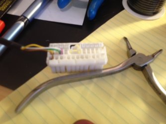
went to wire the 20 pin connector,  EDIT, ignore the following, it is not correct I wired the four wires from the new pickup plate, yellow to pin 9, brown to pin 20, and then I tied the two sense grounds together into one connector, to pin 7.

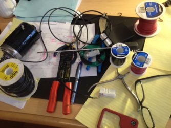
I do not have a crimper for these tiny terminals, and the local tool shop didn't have anything either, so I just used a small pair of dental pliers to carefully make nice neat crimps, no problem. Sliding the connectors into the 20 pin connector was straight forward, just push in hard until it "clicks"

then went to fabricate the wiring for power, ground, and the coils trigger wires, and ran into a snag. I have lots and lots of spools of high quality automotive wire, in several colours. However, it is mostly 12 gauge and 14 gauge, as well as a bunch of 10 gauge and even larger. I do not have any 16 gauge or smaller, I would not typically use those smaller gauges for any of my wiring projects.

Bottom line, the smallest wire I have, 14 gauge, will NOT fit into the  tiny channels in the 20 pin connector. I tried to stick a wire end from a piece of 14 gauge in by itself and it won't enter the small channel in the 20 pin connector. Off to the store only to find that the selection of 16, 18, and 20 gauge wire is almost non existent in the stores local to me that are open on a Saturday afternoon. Did manage to buy a small roll of 16 gauge red, and a small roll of 16 gauge black, which will allow me to wire the power circuit, but I am going to have to go to a specialty supply house to get 16 gauge wire in other colours for the coil wiring.... bloody hell, Monday is a holiday long weekend here, so it will be at least Tuesday before I can get back to this particular project.

crimping these pins is nothing to worry about, quite straightforward, would be easier with the appropriate crimping tool, but I don't think I want to spend $70 to only crimp about 8 pins.......

Paul LeClair
 

Attachments

  • wiring 1.jpg
    wiring 1.jpg
    122.9 KB · Views: 15
  • wiring 2.jpg
    wiring 2.jpg
    80.1 KB · Views: 20
Paul LeClair said:
,, and then I tied the two sense grounds together into one connector, to pin 7. 
stop.  stop.  stop.  i don't understand !!

the white wire from the pick-up board is the +5 V wire, that feeds the pick-ups.  needs to go to pin 17.  well,,  i think it does ??
there is only one ground wire to the pick-up board.

Paul LeClair said:
, brown to pin 20,
no.  brown is the ground,  pin 7 or pin 16.  green is the other pick-up wire.

& i'm guessing that's a Sachse board?  'cause they are white & brown for the +5 V feed & ground.
the latest boards from Redax are red & blue for the feed & ground.
& both boards, use yellow & green for the pick-up wires.

cheers,  Mark
 
Does this help?

TCIP4_BTZ.jpg
 
Pin 17 (+5V) is for appliances, like TPS or MAP. You do not need it for pickups, at least not with original BTZ system...
 
markQLD said:
& both boards, use yellow & green for the pick-up wires.
and,,  i use green pick-up wire for pick-up 1 (pin 9) & yellow wire for pick-up 2 (pin 20).
and if me memory is correct  ???,    coil 1 (pin 1) should be the double coil for the outer pots.
 
TO CLARIFY MY POSTS EARLIER IN THIS THREAD - PLEASE IGNORE MY EARLIER WIRE COLOUR TO PIN NUMBER SUMMARY!

turns out I that while I have an Ignitech ignition module, with Ignitech instructions and wiring schematics and wire colour codes, it has been supplied with an earlier Sasche ignition trigger plate. The Sasche ignition trigger plate wiring colours do NOT match the Ignitech wiring colour codes, the Ignitech colour codes have absolutely NO connection to Laverda wiring colour codes, and I did not have any Sasche instructions.

so, I was wiring the Ignitech 20 pin connector unknowingly applying Sasche wiring colours to the Ignitech wire colour codes, which simply does NOT work as they are completely different.

I am about to take the pins out of my Ignitech connector and sort all this out. I now have the necessary information to do so, thanks so much, Lex!!

All rather entertaining for the electrickery challenged like me, but now I clearly understand how the system needs to be set up. I think.... ;)

Paul LeClair
 
believe you got the very first Ignitech system from us which was shipped before Lex finished making the Series 2 boards
have patience getting those connectors out, need a very thin probe to flick the retainer clip back
good mate of ours destroyed a couple of Ignitech plugs trying to remove those connectors when he first tried to set his system up

 
redax5 said:
believe you got the very first Ignitech system from us which was shipped before Lex finished making the Series 2 boards
have patience getting those connectors out, need a very thin probe to flick the retainer clip back
good mate of ours destroyed a couple of Ignitech plugs trying to remove those connectors when he first tried to set his system up

Hi Red

no worries, looks like the pins have come out without doing any damage to the connector, I pushed a thin flat screwdriver down from the wire side until the retainer clip popped up out of the pin, then used another thin screwdriver to push from the pin end, just pushed each pin out without any strain on the wires.

Lex was a great help, once it was identified that I am working with a Sachse ignition pickup board, which wire colours do not match the Ignitech wiring colour codes, clear sailing from there once I knew what each of the Sasche wire colours represented in relation to the Ignitech........ :D Looking forward to working with the software and maps, this Ignitech ignition module and software package seems really impressive!

Paul LeClair
 
Back
Top