Installation of Sparker TCI P4 Version v80, and Laverda hardware

Hi Cam

really straightforward now I know what the wire colours from the Sasche pickup board represent in relation to the Ignitech.

Pickup Board
brown, ground, to pin 7 or 16
green, sensor 1, to pin 9
yellow, sensor 2, to pin 20
white, 5 volt, pin 17

Coils
orange pin 1 to negative on coil 1 (cylinders 1 & 3)
white pin 10 to negative on coil 2 (center cylinder)

Ignitech Box
switched power from bike, shared with both coils on +, red to pin 13
ground from bike to box, -, black to pin 14

Note: for the wire you need to supply yourself for power (red), ground (black), coil 1 (orange), and coil 2 (white), the very largest that will work with the pins and 20 pin connector is 16 gauge and it is a tight fit, 18 gauge is probably what would work best. Forget about 10, 12, or 14 gauge, just will not work.

Red supplied a significant number of extra pin connectors  (congrats) with the kit, even after having to re pin the connector arising from my earlier errors, I still have a few left over. Will be a while yet before I finish enough of the rest of the bike to be able to start it for the first time, looking forward to utilizing the Ignitech software to set up the ignition!!

Paul LeClair

 
Have fun playing with the Ignitech programming features.

I suspect you might be the kind of bloke to take advantage of some of the Ignitech options. Will we soon be seeing TPS, MAP sensor, fly-by-wire throttle ... ?  :D

Cheers,
Cam
 
Dellortoman said:
Have fun playing with the Ignitech programming features.

I suspect you might be the kind of bloke to take advantage of some of the Ignitech options. Will we soon be seeing TPS, MAP sensor, fly-by-wire throttle ... ?  :D

Cheers,
Cam

Hi Cam

I was certainly considering adding a throttle position sensor to the Dellortto carb rack. Oddly enough I happen to have a spare complete fuel injection rack in my crates of Kawasaki ZX 14 spares that I could probably rob a TPS from, a MAP sensor would be easy enough, and I have had a ton of experience with my Power Commander 5 and Auto Tuner and software and dyno time with my Kawasaki ZX 14........... On the ZX 14 you also have to defeat both the massively excessive fuel enrichening and the timing retardation that Kawasaki uses to limit the bike to 300 kph, both of which obstacles have been overcome on my bike.......... ;)

However, for right now I need to finish the 82 1200 bike build and get it running, I am probably still a month or more away from completion based on my present availability of spare time for garage fun. For now I will be happy with the basics and a good ignition map for the "soft" engine setup of A 11 cams, stock flat top pistons, stock Dellortto carbs with stock exhaust, the only real changes are the carb internals and gutted air box, plus the Ignitech.

Paul LeClair
 
powered the Ignitech box from a bike battery, off the bike, and connected the Ignitech box to my laptop with a converter cable which allows the box to connect to the laptop through a USB port. The converter cable was about $30 at my local computer parts store.

the Ignitech box was "virgin", astonishing how simple it was even for an idiot like me to "read" the box, upload an initial timing map into the software, then "program" it to the ignition box (click of a mouse in the software), then verify the install, then fiddle with the ignition map views, table view, 2D view, 3D view, and check out the rest of the software. Bloody hell, everything is controllable and adjustable, although I learned that without a TPS being used, the ignition map goes from 100 points to 10 points, I can see a TPS install in my future...

now I need to figure out dwell. Each coil needs a certain amount of time to receive power into the primary winding, to then be able to fire a spark plug when the coil is trigered. In points ignitions that is expressed as a certain number of degrees of distributor rotation, usually 30 - 40 degrees, which gets adjusted as a basic function of adjusting the mechanical points gap. In electronic ignitions, I have seen dwell set as an equivalent percentage, usually around 45 - 50 degrees.

In the Ignitech software, dwell is expressed as a function of time and is adjustable, base settings seem to be a range of 0.1 ms to 4.3 ms, and you can set roughly five different parameters for dwell. Has anyone given programming the dwell any thought? I don't know how fractions of a ms relate to degrees of distributor rotation, for example, or how much time a coil needs to saturate between each firing of a plug, particularly the coil that has to fire two plugs? Anyone?

Paul LeClair

EDIT
here is what the Ignitech FAQ on their web site says about dwell:

It is possible to set up excitation time of inductive coil by Ignitech ignitions?
Excitation time can be changed only in ?Special setting? by inductive ignition. There are two
setting. Short is 1ms and one eighth of revolution time. Long is 3 ms one eighth of revolution
time. This time is set automatically by selection of certain bike. This time is set according
common coil type used on this bike. Short excitation time is for inductive coils with primary
resistance less than 2 Ohm and inductance is less than 6 mH. Long excitation is set for coil
with higher resistance and or higher inductance.
If long excitation is set for coil with low resistance and low inductance coils are overheated
and can be destroyed. If short excitation is set for coil with high resistance and high
inductance spark energy is lower.
Ignitech injection units have no possibility to set excitation time. It is set automatically by
selection of certain bike. This time is set according common coil type used on this bike.

 
after reviewing the IgniTech software and related manual, it appears possible to use modern LOW primary resistance coils with the Ignitech, in place of the old fashioned 3 ohm high primary resistance coils that were necessary with points and primitive ignitions.

has anyone actually tried modern low primary resistance coils on  Laverda triple with the IgnitTech, yet?

Paul LeClair
 
Hi Paul,

I was considering that but am far behind with my project currently due to a house we bought recently and that needs a massive investment of time, labor and money to bring it back to its initial glory (built 1938, extended 1964, nearly nothing done ever since... we even found the original kitchen built 1938 with the original stove from K?ppersbusch in perfect condition).

Am reading your findings with great interest, will help me on my project next winter, I am sure!! Sorry not to be able to support with first hand information though.

keep it coming, you seem to be on a very good way!!
 
Hi Lothar and all

just be careful to remain aware that I am working with a Sasche ignition pick up board and wiring colours, which wiring colours do not match the Ignitech schematics and wiring colour codes, and that was not clear to me at the start of this process. I know Red is developing or has developed his own ignition pickup board which I am guessing he will be primarily supplying going forward, and I don`t know what it`s colour coding will be. So be very careful about my wire colour references to Ignitech pin numbers, they apply only to wiring the Sasche ignition pickup board.

just be aware that Red, and Lex (who appears to be assisting Red) have been absolutely excellent with their support in sorting my initial confusion out, the product is very well supported.

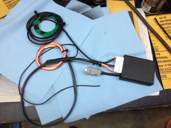
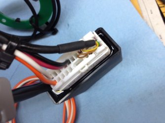
below, two photos of the finished result ready for installation on the bike. The only thing missing from the photos is the two piece machined aluminum crank end trigger that Red manufactures to signal the ignition pickups.

Paul LeClair
 

Attachments

  • Sasche and Ignitech 1.jpg
    Sasche and Ignitech 1.jpg
    125.5 KB · Views: 20
  • Sasche and Ignitech 2.jpg
    Sasche and Ignitech 2.jpg
    94.6 KB · Views: 16
I reckon people who place any credence in wire colours shouldn't be messing about with the electrics on old Italian bikes.

Wire colours are only useful to identify the ends of the same wire where it disappears into, and re-emerges from a sheathed wiring harness. Even then it's not 100% reliable. I've found bikes with PO bodges where a wire has been joined to a different colour inside the wiring harness sheath. I've probably even done such a bodge myself.  :D

Cam
 
Paul LeClair said:
,, and I don`t know what it`s colour coding will be. Paul LeClair 
& i no nothing.  i come from da cane fields.    ;)

markQLD said:
& i'm guessing that's a Sachse board?  'cause they are white & brown for the +5 V feed & ground.
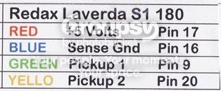
the latest boards from Redax are red & blue for the feed & ground.
& both boards, use yellow & green for the pick-up wires.
markQLD said:
and,,  i use green pick-up wire for pick-up 1 (pin 9) & yellow wire for pick-up 2 (pin 20).
and if me memory is correct  ???,    coil 1 (pin 1) should be the double coil for the outer pots.

Redax-board.jpg
 
Dellortoman said:
I reckon people who place any credence in wire colours shouldn't be messing about with the electrics on old Italian bikes.

Wire colours are only useful to identify the ends of the same wire where it disappears into, and re-emerges from a sheathed wiring harness. Even then it's not 100% reliable. I've found bikes with PO bodges where a wire has been joined to a different colour inside the wiring harness sheath. I've probably even done such a bodge myself.  :D

Cam

Hi Cam and all

that is exactly what I was working with, without knowing it was a Sache board. Four wire ends poking out the end of a sheath, the other end sealed and no way to identify any of the four except by colour.....

Great to see Mark Muir's post clarifying the new wire colour coding on the new RedAx produced boards.

all of this is really simple, I just got off track at the beginning.

Paul LeClair
 
Back
Top