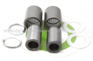
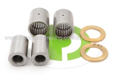
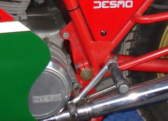
Laverda 500 swinging Arm Bearings

The list of Original Laverda parts can be found in the 350-500 parts book. https://damclassicracing.com.au/1979_laverda_350_500_parts_book/
The spindle is available https://damclassicracing.com.au/34250234-spindle-swingarm-500/
The OEM bushes are available (1 listed at present. I'll put the others into the shop soon) https://damclassicracing.com.au/50210980-bush-silentbloc/

Contact Us https://damclassicracing.com.au/contact-us/  if you want to look at the non-standard kit options.
 
Greg Parish said:
The list of Original Laverda parts can be found in the 350-500 parts book. https://damclassicracing.com.au/1979_laverda_350_500_parts_book/
The spindle is available https://damclassicracing.com.au/34250234-spindle-swingarm-500/
The OEM bushes are available (1 listed at present. I'll put the others into the shop soon) https://damclassicracing.com.au/50210980-bush-silentbloc/

Contact Us https://damclassicracing.com.au/contact-us/  if you want to look at the non-standard kit options.

Thanks for you reply I've emailed you.
 
Hello, this is  quite an simple job apart from removing the original bushes which can be a bastard of a job, I ended up using heat and a press (obviously before repainting)

You need two bearings, two outer bushes, a central bush / spacer and two outer shims, when you fit the swing arm back you can tighten the spindle nuts until you get a nice free operation, do this without the shocks on so you can feel what is happening

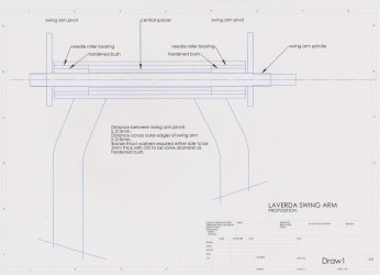
My drawings attached show what I found when I did mine a while ago for racing, good fix, once its done you can forget it other than checking for play once in a while which you can take out by a little tweak on the spindle nuts, plenty of grease during fitting
 

Attachments

  • Laverda swing arm.pdf
    Laverda swing arm.pdf
    135.8 KB · Views: 14
  • Laverda Swing arm proposition.jpg
    Laverda Swing arm proposition.jpg
    131.7 KB · Views: 92
Fitz said:
Hello, this is  quite an simple job apart from removing the original bushes which can be a bastard of a job, I ended up using heat and a press (obviously before repainting)

You need two bearings, two outer bushes, a central bush / spacer and two outer shims, when you fit the swing arm back you can tighten the spindle nuts until you get a nice free operation, do this without the shocks on so you can feel what is happening

My drawings attached show what I found when I did mine a while ago for racing, good fix, once its done you can forget it other than checking for play once in a while which you can take out by a little tweak on the spindle nuts, plenty of grease during fitting

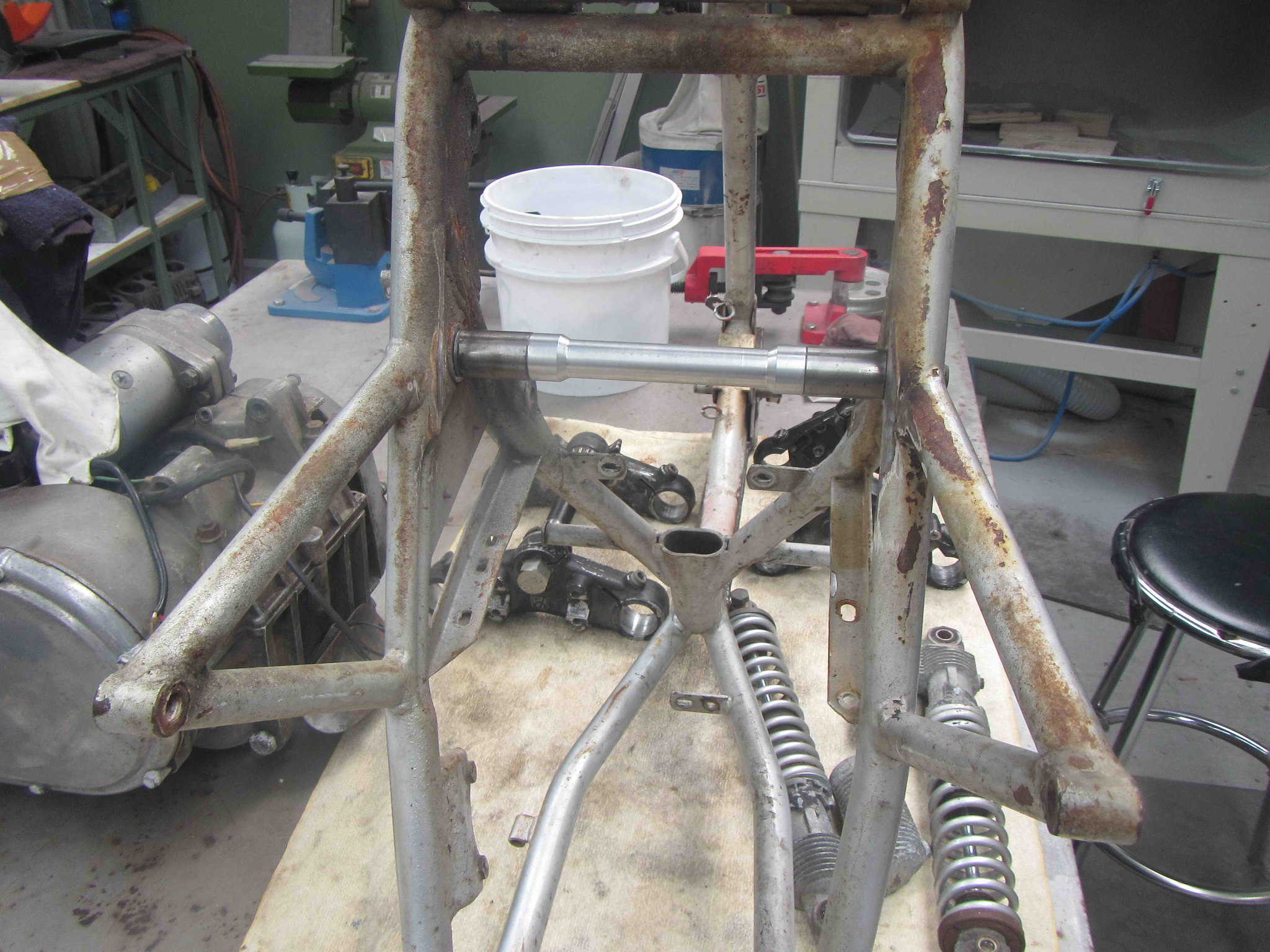
Brilliant thanks as I am about to paint the frame so it's a good time to do this.
Pat :)
 
Fitz said:
Hello, this is  quite an simple job apart from removing the original bushes which can be a bastard of a job, I ended up using heat and a press (obviously before repainting)

You need two bearings, two outer bushes, a central bush / spacer and two outer shims, when you fit the swing arm back you can tighten the spindle nuts until you get a nice free operation, do this without the shocks on so you can feel what is happening

My drawings attached show what I found when I did mine a while ago for racing, good fix, once its done you can forget it other than checking for play once in a while which you can take out by a little tweak on the spindle nuts, plenty of grease during fitting

Sorry, but that is very, very wrong, and potentially quite dangerous.

The spindle and the centre bearing races with distance tube should be done up TIGHT between the frame gussets.  The assembly needs to be a SNUG FIT between the gussets to begin off with.  Needle races are non-adjustable, once they're knackered, they require replacing.  The swingarm should pivot around the central bearing race/tube assembly, thrust washers taking up side play of the swingarm pivot tube between the frame gussets.

What you're doing, is letting the entire swingarm assembly pivot around the spindle and stressing the frame by "tweaking the spindle nuts", with danger of the spindle locating holes in the frame wearing because the spindle isn't tight.  By tweaking the spindle nuts, you're simply further binding the swingarm between the frame gussets.  You are also inducing shear loads on the spindle, something it isn't designed for.

I recommend you have a good think about this and compare your set up with that of the triples.

piet
 
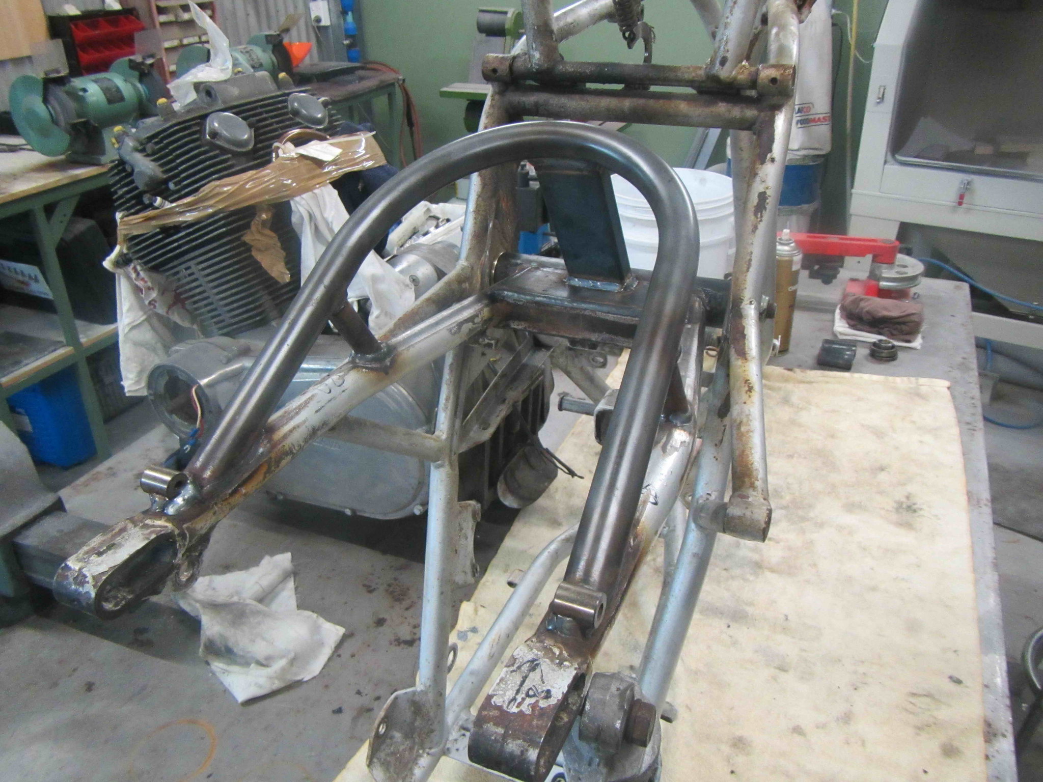
Piet is referring to this set up, inner hardened bushes are a snug fit into the frame using a custom spacer and are locked in place by the spindle nut
Bronze thrust washers that limit the swingarm side movement fit over the hardened bushes and thus allow the swingarm to pivot freely on the needle bearings
in the 2nd photo you can just make out the bronze thrust washers between the frame and the swingarm, their OD is slightly larger than the swingarm tube
photos taken of Mike's race bike during the build

19th Sept MN 500 swingarm modifications 1
19th Sept MN 500 swingarm modifications 3
 
The 'thrust washers' were supplied from Laverda made from Nylon on the later models. Part no. 33116499. It is still good practice to make these out of Bronze for racing as we did on our bikes also but nylon is sufficient and is standard replacement in the swingarm kits.
https://damclassicracing.com.au/22805523-bearing-set-swingarm-14mmhk25x32x38-nylon/
 

Attachments

  • 22805523 Bearing set swingarm 16mm HK25x32x38 Nylon Washer_wm  .jpg
    22805523 Bearing set swingarm 16mm HK25x32x38 Nylon Washer_wm .jpg
    180.9 KB · Views: 19
  • 22805523A Bearing set swingarm 12mm HK25x32x38 Bronze Washer_wm  .jpg
    22805523A Bearing set swingarm 12mm HK25x32x38 Bronze Washer_wm .jpg
    213.3 KB · Views: 19
sfcpiet said:
You are also inducing shear loads on the spindle, something it isn't designed for.

Sorry Piet, while you're correct in your critique of Fitz's drawing, that comment about shear load doesn't make sense to me. The swingarm spindle is under axial tension when you do up the nuts, but the working loads are pretty much all shear, so that's exactly what it's designed for. There are no bending loads, and you'd only get torsional loads if a bearing seizes.
 
When everything is tightly clamped down, the spindle will be in tension and the clamping force between the frame and tube assembly will/should eliminate shearing forces at the spindle to a great degree, if not totally.  Once the spindle is loose, as in Fitzs' example, it will be fully open to bend and shear forces, as these will all be transmitted straight into the spindle.

Another example of this type of fixing is the cam joint in the 750 twins.  The cam halves are held together with 3 x 6mm studs through the timing sprocket, drive is tranmitted through friction/clamping forces attained by tightening the studs.  Once these studs loosen just a tiny bit, the whole plot simply dissolves, as the studs don't stand a chance against the shear forces.

piet
 
OK. I can see your reasoning that some of the shear load across the frame-swingarm joint is carried by friction between the end of the inner bearing race and the frame plate. But I reckon the major proportion of the load would be carried by the shaft itself. The nuts on the ends of the swingarm spindle are there mainly to hold it in place. 

I can't claim to know the relative distribution of loads for sure, maybe friction does most of it, or maybe not.  But I'd be very confident in saying that the designers would have sized the shaft to carry the all the suspension loads on its own, assuming zero contribution from friction between components. It would be too risky to do otherwise because they'd want the bike to be bulletproof safe if the nuts weren't done up to the correct tension.

Some contemporary bikes that have a similar sized swingarm pivot shaft (my Ducati for instance) don't have nuts on the ends of the shaft at all. It's just held in position by a pinch bolt at each side of the frame (photo below).  There's no compressive load on the bearing/spacer stack, and therefore no possibility of shear load being carried by friction between the components. All the shear load is carried by the shaft. End float is controlled by shims if necessary.  There's not much wrong with Ducati frames. They're renowned for good handling.
 

Attachments

  • swingarm pivot.JPG
    swingarm pivot.JPG
    116.7 KB · Views: 30
Cam,

Please compare the size of the Ducati axle with the Laverda spindle, apples and pears, completely different loadings.  The Duc axle takes up shear loads, the same as the Laverda AXLE or bearing/tube assembly.

Easy to find out how it works.  Just loosen your Laverda swingarm nuts a couple of turns and go for a lengthy ride.  Then pull the spindle and you will find markings that weren't there before...

piet
 
sfcpiet said:
When everything is tightly clamped down, the spindle will be in tension and the clamping force between the frame and tube assembly will/should eliminate shearing forces at the spindle to a great degree, if not totally.   Once the spindle is loose, as in Fitzs' example, it will be fully open to bend and shear forces, as these will all be transmitted straight into the spindle.

Another example of this type of fixing is the cam joint in the 750 twins.  The cam halves are held together with 3 x 6mm studs through the timing sprocket, drive is tranmitted through friction/clamping forces attained by tightening the studs.  Once these studs loosen just a tiny bit, the whole plot simply dissolves, as the studs don't stand a chance against the shear forces.

piet
Spot on, Piet. When the spindle is properly torqued, it needs a load in excess of 1.5 metric tons to break up the friction forces and get the spindle under shear loading. You won't see that happen riding the bike, except maybe someone crashing his car/truck heavily into the bikes rear end.
 
Back
Top