Little help required with 1974 SF2 wiring

Hi Steve,

Yes, its good old blighty, actually the Scottish Highlands.

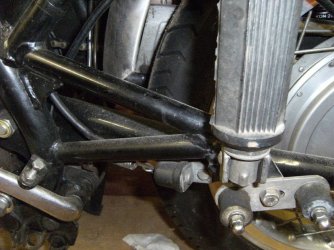
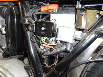
There should be 1 photo of the fuse box area and 1 of the rear brake switch attached. (Resizing didn't work, hence 2 emails!). I believe most of the wiring is original, but the wire to the flasher unit has clearly been crudely spliced - that's a job for over the winter.

On my bike the main terminal block is under the front of the seat and enclosed in a black plastic box - are your connectors up near the coils?

Hope these images help ? let me know if you need any more.

Andrew.
 

Attachments

  • rsz_andrews_pictures_244.jpg
    rsz_andrews_pictures_244.jpg
    122.1 KB · Views: 31
Hi,

Here is the second one - rear brake light switch.

Regards,

Andrew.
 

Attachments

  • rsz_andrews_pictures_243.jpg
    rsz_andrews_pictures_243.jpg
    111.8 KB · Views: 25
Tippie said:
Steve.
If you are still stuck with the diode. Normally they are marked  + (anode) and - (cathode). Current can only flow from the anode to the cathode. The wiring diagram symbol is like an arrow and current flows in the direction of the arrow.

I found that the diagram (in the green book) for the 3C has the diode direction the wrong way around. It was corrected on the later 3CL diagram. I haven't checked the SF wiring diagram. It is probably OK but don't take it as gospel until you've checked it. It's easy enough to work out if you follow the logic of the circuit.

Cheers
Cam
 
Cam. I actually thought that it looks to be shown wrong in the diagram on Laverdapedia site for the SF2. I understood it was to prevent current from being able to flow into the main system from the parklight wire from the ignition switch if the bike is left in "park" without the key in. The diagram shows the opposite doesn't it? I didn't want to confuse the issue so pointed out what the diagram shows.
I have never left any bike in "park" without the key and don't use that wire in my abbreviated harness. Cheers Lee
 
Am having a little difficulty with headlamp circuit  with regard to LH switchgear. The 3 position switch marke - S - is the headlaight on off switch. Can someone tell me why there are 3 positions and what is supposed to operate in each position.

I assume the switch on the left of it marke P H L is for Park Low and High beam ?

Thanks
 
Steve
The - s - side: Lower  - pos is all lights off. Middle S pos is parklights on. Forward - pos is headlight on as well as park lights.
The outer HLP side: Lower H pos is high beam (blue wire from memory). Middle L pos is low beam (White wire). Forward P pos is spring loaded so that the switch cannot be left in this pos but returns to L. It is "Pass" for flashing high beam for overtaking or warning purposes (radar ahead!!) and will flash high beam even when the lights are turned off.
If you have the switch open and it shows any sign of filth or corrosion you can carefully dismantle it and rub the contacts with fine emery to renew them. Reassemble with some recommended electrical quality grease especially on the spring loaded ball sections so that it all moves  nicely.
Cheers
Lee
 
Cheers Lee, all becoms clear. The spring part for the pass function is missing, so it seemed to be a
3 position switch, which is what confused me.  I'll stop asking dumb questions when I get past this electrical part and back on the nuts and bolts............I hope.
Of course, if Scott would run up from the Hill Country and spend an hour here, I could save weeks and a few dozen posts ;)
 
Back
Top