

HansGerch
Full member
Hi,
this is for better overview and design freeze, and for discussion.
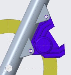
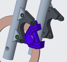
I created a CAD model consisting of leg, rotors, caliper, pads and adapter.
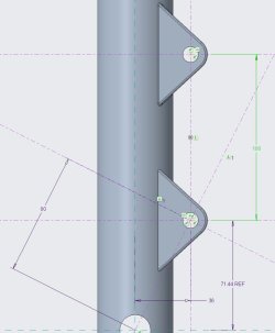
Model geometry is exact for rotor and caliper, leg design is based on measured dimensions for the fixation points.
This gives a very good match for the 280 setup, caliper is aligned to center, piston radius on 120.25 (should be 119 according Brembo)
Pad to rotor placement is good.
That means, leg geometry is sufficient exact.
For the new position of the caliper:
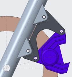
I moved the center of the piston from radial 120.25 to 129, see Brembo drawing.
Then i rotated 19°, all refering wheel axis.
This new point ist new pistoncenter, new orientation of caliper is then defined through a line wheelaxis/this point.
Now there are four points, two on legs (based on measurement), and two theoretical exact points for the new caliper fixations.
The resulting part is just to join these points and a design proposal.
Attached stp files for LHS and RHS, the pics are true to scale, refer the 280/300 diameter.
Outlook:
Design is a very first guess. Nothing has been calculated or checked for stress or optimated for weight.
Rotation angle can be less than 19°, even a hole in the area of the lower interface is possible...
I want to check a version with less angle.
Feel free to comment, correct...
PS: 328g weight for aluminium
PS2: Thanks to Stéphane, Marnix and Piet.
Thanks, Roland
Attachments
Last edited:


