You are using an out of date browser. It may not display this or other websites correctly.
You should upgrade or use an alternative browser.
You should upgrade or use an alternative browser.
Montjuic wiring issue regulator.
- Thread starter TonyP
- Start date



Hi,
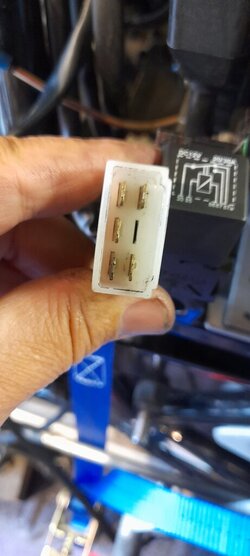
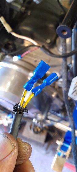
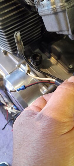
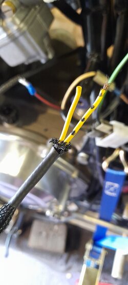
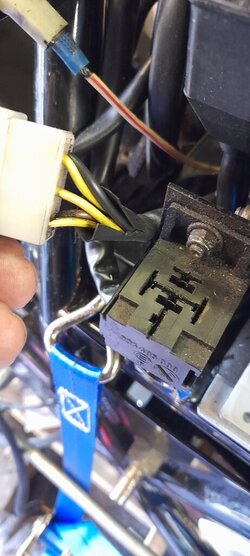
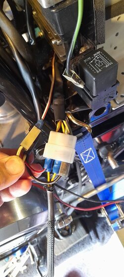
Sorry I am just getting my head around posting on the site. I am building a Monjuic for a friend and struggling in working out the terminations for the regulator. I have a wiring diagram which does not reflect what I have. Can anybody help me please I have attached a number of pictures so you can see my predicament.
Regards Tony.
Sorry I am just getting my head around posting on the site. I am building a Monjuic for a friend and struggling in working out the terminations for the regulator. I have a wiring diagram which does not reflect what I have. Can anybody help me please I have attached a number of pictures so you can see my predicament.
Regards Tony.

Rob
Hero member
- Location
- Midlands, UK
Looks like you're trying to use a 3 phase reg/rect (3 yellow wires in plug) with the single phase two wire Monty alternator.
It would help to know the make and model of the reg/rect. I'm assuming that the 6 way plug is from it? The brown wire is likely the positive 12v dc output and black is the ground wire but would be good to check with a wiring diagram before blowing it up,
You should also bin those horrible pre-insulated spade crimps - they seldom provide a reliable connection to the wire.
It would help to know the make and model of the reg/rect. I'm assuming that the 6 way plug is from it? The brown wire is likely the positive 12v dc output and black is the ground wire but would be good to check with a wiring diagram before blowing it up,
You should also bin those horrible pre-insulated spade crimps - they seldom provide a reliable connection to the wire.

FWIW, you can use any of the 3 yellow wires to connect to the two alternator wires ( was unaware the Monty was single phase and i have worked on one, tah Rob ). With RR connected to alternator and not connected to bike electrical system, using a properly configured multimeter, start the engine and identify the polarity of the two DC output wires in the RR plug. Not sure from the photo exactly what is already on the bike electrical system. Should you use constant pressure crimper tool ( ratchet ) the insulated faston connectors ( 6.4m/m from memory ) will be reliable, good crimps embose the die size numbers onto the lug plastic body, ie "2.5".
Hi Rob.Looks like you're trying to use a 3 phase reg/rect (3 yellow wires in plug) with the single phase two wire Monty alternator.
It would help to know the make and model of the reg/rect. I'm assuming that the 6 way plug is from it? The brown wire is likely the positive 12v dc output and black is the ground wire but would be good to check with a wiring diagram before blowing it up,
You should also bin those horrible pre-insulated spade crimps - they seldom provide a reliable connection to the wire.
It is a Shindegen SH530-12. 1.0
The wiring diagram doesn't help the plug indicated is a different configuration. The connectors are for trial purposes only once I get it sorted they will be changed.
I agree it seems to be a 3ph reg used in a single phase generator. It must have worked as the bike i assume came from Slaters like this.
Reg Tony thanks for the help and look forward to your comments.
I haven't got as far as starting the engine but what I have figured out I think is as follows.
Yellow wires are not an issue.
I have a white and Red out of the RR this connects to the 25amp fuse via a white cable in the loom. The black wire out of the RR is earth. Which on leaves the brown out of the RR which I have connected to a blue and red in the loom which goes to the charge light in the rev counter. I still don't have an illuminated charge light when the ignition is on. But reading some other info might not be the case as its not a built in function of this RR. Any further help would be greatly appreciated.
Reg Tony
Yellow wires are not an issue.
I have a white and Red out of the RR this connects to the 25amp fuse via a white cable in the loom. The black wire out of the RR is earth. Which on leaves the brown out of the RR which I have connected to a blue and red in the loom which goes to the charge light in the rev counter. I still don't have an illuminated charge light when the ignition is on. But reading some other info might not be the case as its not a built in function of this RR. Any further help would be greatly appreciated.
Reg Tony
Attachments


The brown wire is the actual regulating voltage output sense wire on the RR, to mitigate endless drama, connect it to the Red/White wire direct, it will slow discharge the battery over a long period of no engine running periods. Additionally the Black wire from the RR as best practise connected to the actual negative terminal of the battery. This has been addressed endlessly over several decades on the forums. HTH j. BTW the connection you have made of the brown wire will most probable cook the battery if it works at all.I haven't got as far as starting the engine but what I have figured out I think is as follows.
Yellow wires are not an issue.
I have a white and Red out of the RR this connects to the 25amp fuse via a white cable in the loom. The black wire out of the RR is earth. Which on leaves the brown out of the RR which I have connected to a blue and red in the loom which goes to the charge light in the rev counter. I still don't have an illuminated charge light when the ignition is on. But reading some other info might not be the case as its not a built in function of this RR. Any further help would be greatly appreciated.
Reg Tony
Firstly I really appreciate your help many thanks. The black wire connection now gives me the answer to why there was an additional earth wire on the RR plug when I received the boxes of bits that were supposedly a Laverda. Just for clarity the brown out of the RR needs connecting to the Red and white out of the RR do I need to connect the white wire from the loom into this connection which goes to the fuse box.The brown wire is the actual regulating voltage output sense wire on the RR, to mitigate endless drama, connect it to the Red/White wire direct, it will slow discharge the battery over a long period of no engine running periods. Additionally the Black wire from the RR as best practise connected to the actual negative terminal of the battery. This has been addressed endlessly over several decades on the forums. HTH j. BTW the connection you have made of the brown wire will most probable cook the battery if it works at all.
The blue and red wire which goes to the charge light is now redundant.
Many thanks kind regards Tony
Hello Tony, step by step progress. Usually the input to system main fuse will be connected to the DC output of the RR ie Red White wire/connector. There is a connection diagram in the library here i did for SH530 and 532 RR's see if i can link it. While it indicates connection of the brown wire to switched 12V ( ignition switch ) the wiring and switches have to be in solid reliable form to work correctly, any voltage losses in the system will add charging voltage to the battery, HTH j.
 laverdaforum.com
Any - Recommended alternator - 3 phase reg/rect connections
Shindengen SH530-12 shown, but valid for all 3 phase regulator/rectifiers with permanent magnet alternators
laverdaforum.com
Last edited:
Hi iis_iis.
I have connected the wireing as you described, could I just confirm that connecting the blue and red wire within the loom from the charge light will be sufficient to act as the feed from the ignition switch as it carries 12v permanently. In long periods of no use we can disconnect this cable to stop it draining the battery.
I have replaced the generator terminals with good quality crimps and soldered them also. I will do the same with the Red and white connection.
Thanks once again regards Tony.
I have connected the wireing as you described, could I just confirm that connecting the blue and red wire within the loom from the charge light will be sufficient to act as the feed from the ignition switch as it carries 12v permanently. In long periods of no use we can disconnect this cable to stop it draining the battery.
I have replaced the generator terminals with good quality crimps and soldered them also. I will do the same with the Red and white connection.
Thanks once again regards Tony.
Rob
Hero member
- Location
- Midlands, UK
Hope John doesn't mind me jumping in -
Assuming the instrument wiring is standard, I'd suggest not! The blue/red wire is being fed through the charge warning lamp from an ignition switched supply via the fusebox. So it shouldn't be permanently live - which is good. Nor will it be providing an accurate indication of battery volts due to the charge lamp resistance - which is bad!
There's a wiring diagram in the library - https://www.laverdaforum.com/xf/resources/54/ - p.139 of the 350/500 workshop manual
Assuming the instrument wiring is standard, I'd suggest not! The blue/red wire is being fed through the charge warning lamp from an ignition switched supply via the fusebox. So it shouldn't be permanently live - which is good. Nor will it be providing an accurate indication of battery volts due to the charge lamp resistance - which is bad!
There's a wiring diagram in the library - https://www.laverdaforum.com/xf/resources/54/ - p.139 of the 350/500 workshop manual
Dear All.
I can't thank you enough for the help and patience you have shown in helping me get this sorted. I am not great electrician my skills are more mechanical for sure.
It's been a pleasure in chatting with guys who know what's needed.
Reg Tony.
I can't thank you enough for the help and patience you have shown in helping me get this sorted. I am not great electrician my skills are more mechanical for sure.
It's been a pleasure in chatting with guys who know what's needed.
Reg Tony.
Attachments

After you Rob, saves me a typing fingers cramp....no problem, grin. As you indicate, there are best choices and not so reliable choices. Sense wire via incandescent lamp would/should work, though drawing low current through various types of metals can produce high resistance contact to contact over time, or lamp going open circuit. Wetting current is a new topic here, sure the lads will be well pleased at the prospect.... a wry smile here. j.Hope John doesn't mind me jumping in -
Assuming the instrument wiring is standard, I'd suggest not! The blue/red wire is being fed through the charge warning lamp from an ignition switched supply via the fusebox. So it shouldn't be permanently live - which is good. Nor will it be providing an accurate indication of battery volts due to the charge lamp resistance - which is bad!
There's a wiring diagram in the library - https://www.laverdaforum.com/xf/resources/54/ - p.139 of the 350/500 workshop manual
Go Tony, your doing well, your appreciation is noted, above that your willing to learn new skills, at times that learning process is daunting or similar. Once there was a time any "new" noise from the Laverdas' caused panic.... then new skills were acquired in restoration and repairs, over time. After some time, even a nuked crank did not produce panic, out with the crank pressing jig and fix it... self satisfaction has much merit. No doubt Tony you will be well happy, in bike and self, well done you. j.Dear All.
I can't thank you enough for the help and patience you have shown in helping me get this sorted. I am not great electrician my skills are more mechanical for sure.
It's been a pleasure in chatting with guys who know what's needed.
Reg Tony.
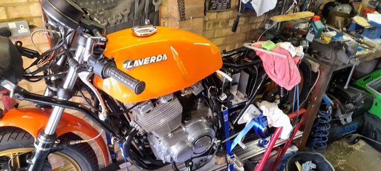
I think I will be thrilled when it's done cocidering I got a frame two wheels and four boxes. As I said the bike is not mine it's a good friend of mine who took it apart broke a piston ring and put in boxes and left it. I could not leave such a mint bike in such a state, so I offered to rebuild it for him.
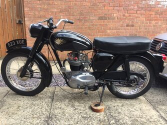
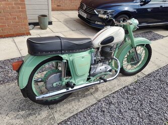
I think he will be chuffed with the end result, my bikes are not so special pictures attached.
I think he will be chuffed with the end result, my bikes are not so special pictures attached.