Odd bearing damage

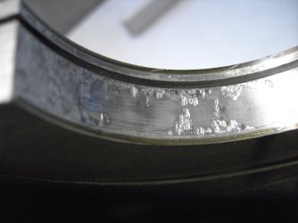
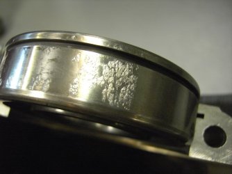
I don't tink I've ever taken one apart that has not shown some sort of fretting and or spinning damage. Read a fair bit about harmonic vibration in crankshafts which is most likely the cause of this damage. Not much you can do about it other than clean everything up and put it back together with a little 638 bearing fit. It is a fine line when machining cases to take bearings, the fit must be good to hold the bearing outer tight enough to stop it moving yet not too tight as to crush it and close running clearances up, throw differential expansion into the mix and it is easy to see why the mains are inclined to move about a bit under duress.
    Straight forward job to check the crank for run out and phase anommalies at home using fairly basic tools and a bit of immagination. Buy a cheap dial test indicator and a degree wheel and spend a happy evening twirling your crank around in the lower case.


  Keith

 
Good point Keith, I do have a DTI too!  Might save me developing arms like Grant's avatar must have!

I had read that some SFC1000s were not as smooth as they should have been - even quite coarse - damaging the 120 engines' smoothness reputation.  Maybe this was one of them, though I also wonder whether it may be just that one or more crankcase stud nuts was perhaps not tight enough.  The engine had never been apart before and is fairly low mileage.

Cheers, Andy 
 
Grant, I'm getting worried about your monkey fixation, cheeky monkey!  :D
 
Andy,
The lab certainly seem well clued up, are you going to take one of the bits pictured in as well?
I can see the shiny 'scribbles' on the surface of both faces (I take it this is the movement), and some darker areas (?).
 
Andy,

Like Red and Keith, I've come across lots of this type of damage, mainly in hard-worked 120s, although the odd 180 with a bit of power will also display it.

Seems to be due to pressure/movement within the bearing seat, you will find corresponding alloy deposits on the bearing races.  At least this keying process prevents the bearing from spinning. :D

As has been suggested, all you can do is check the crank for excessive run-out, unlikely, and stuff it back together with a couple of drops of Loctite bearing adhesive.

piet
 
Keith and Piet
How have motors put together with loctite bearing retainer looked at disassembly further down the track. I?ve found this pitting and rotation of the outer race on all high mileage SF cases; it was the reason I bought my spare SF which was totally run-down but low mileage, as my own bearings were so loose in the cases. I had used bearing retainer on the occasions the cases were opened and it hadn?t helped and it was suggested that it in fact introduces a weaker substance between the bearing and case which hinders proper clamping. My brother recently reassembled an SF motor that had steel bearing-lands inserted and line-bored to reclaim the cases. All of the SF cases I?ve seen on e.g leboncoin have plenty of visible bearing-land wear.
So how do the triple cases seem in this regard?
Ciao
Lee
 
Lee,

Loctiting the bearings definitely helps keep the bearings in place.  A racing triple turns up at the OCT workshop quite often, no movement of crank or gearbox shafts to be seen between tear-downs.  This particular engine was not originally built by us, we only repair it... the crank now seems to hold up well since I rebuilt it, the gearbox has given problems because the owner prefers to run the bike without a rear-wheel cush drive.  Top-end was re-done by OCT, no problems at all there... :D

Zane crank and gearbox bearings regularly spin in the cases, only fix here is Loctite!

I tend to think that bearing land wear can be traced to either hard-worked or poorly set up engines!  There's far too many twins out there that vibrate far more than they need to.  Ham-fisted repairs, non-synched and worn-out carbs or unequal ignition timing can cause the twins to turn into instruments of torture.  In time, the ensuing vibes will take their toll on engine components as well as on the chassis and the rider!!

piet
 
sfcpiet said:
Zane crank and gearbox bearings regularly spin in the cases, only fix here is Loctite!

Don"t know why but I was pretty sure that you would speak about zane cranks!!  :D
 
I decided to replace the damaged main bearing as replacement SKF bearings are readily available at reasonable cost.

Now the fun starts, how to remove the old bearing when there is so little clearance with the crank cheek? I tried to source a large bearing separator, as the one I have is too small.  However, I have not found one yet that is big enough that does not look like it should be in a shipyard! Wolfgang advised that the factory used to supply an 'L' profile ring that slides onto the bearing and is held in place by the
snap ring - a legged puller can then be used without difficulty. Good idea, but they are not available.

I tried the ILOC tool store without success and I do not have facilities to make one at present; plus, the engineering firm I use is on a break at the mo.  Ao, does anyone perhaps have the ring that Wolfgang described that they would perhaps be prepared to loan for a few days?

Cheers, Andy
 
Andy, this is how I get them off
is the large bearing separator
come off fairly easily

HTH
Red
 

Attachments

  • Crank bearing puller.jpg
    Crank bearing puller.jpg
    191.6 KB · Views: 86
Hi Red,

That is the type of seperator I was trying to find, but the only ones I have found so far have a very thick leading edge to the cone.  Maybe I am looking at Ting Tong stuff and will have to go up market. Yours looks the business, but I was hoping to avoid paying for SP or the like for probably a one-off use.  Maybe I will just have to stop being a pikey and get spending.  I do much prefer spending on proper quality tools if their use will justify it.  In this case, engine built or not built..... hmmmmm....time for Google!

Andy
 
I was going to suggest Sykes Pickavant but it looks like you are already on the case.
http://sykes-pickavant.com/Portals/0/PDFs/Pullers/Pullers%20&%20Separators%20-%20Bearing%20Separators.pdf

It is good stuff though.
 
Thanks for the link Simon!

My problem with many of these tools is that the taper edge on the splitter is far too wide - 2-4 mm - when it needs to be no more than 1 mm ideally to get started between the bearing and the crank.

Also, much of the SP kit is way over ?100, which is why I have hesitated so far. But then the cheap stuff can be really crude.  Decisions, decisions........

Cheers, Andy
 
Just taken delivery of a Sealey bearing separator and with a hydraulic ram, similar to the one in Red's photo.  The sparator was for 75 mm -105 mm bearings so the 80 mm bearing was theoretically well within its range and should have been a straightforward job.  However, the separator cones only just edged behind the race on nearly the limits of the nut threads (cannot think how it would cope with a larger bearing) and despite oiling all surfaces and really leaning on the large 24 mm seaparator nuts with long spanners, the bearing refused to budge - the quite steep cone angle was not helping.  It was only when I resorted to playing a blowtorch on the bearing that eventually there was a loud crack as it shifted fractionally and then, with repeated heaving on the spanners and more heat, it finally moved sufficiently for the separator halves to get far enough behind the bearing for the ram to be used - that finished the job in seconds!  That was not easy.

I have placed the crank in the lower case with the bearing removed and put a (imperial) dial guage on the bearing land. With full rotation of the crank, I get a maximum deflection of just under 0,003" (0,0762 mm), which gives a run-out of approx 0,0015" (0,0381 mm).  The RGS manual shows run-out being measured at the two centre bearing positions (?) and quotes a run-out limit of 0,05 mm (0,10 mm max deflection).  As I have not measured in the way described, the figures in the manual may not be the ones to use but I am pretty comfortable with the readings I achieved - unless anyone who does this sort of thing for fun can see a flaw in the way I have done it?

Cheers, Andy
 
Nothing wrong using a seperator for removing the bearing Andy, but I find the factory tool more than ample.  Any old 2- or 3-legged puller that fits behind it is enough to remove the bearing, a 2 minute job at the most!  The factory tool is a simple stepped ring that fits behind a snap ring inserted into the groove in the bearing and leaves enough space behind it for a puller to be applied.  A snap ring is provided with the new bearing, and because it isn't needed in the engine, it can be used to remove the old bearing and kept for future use.

Your measured total deflection of 0.07mm is tolerable, but it can be reduced.  When rebuilding, I often get to as low as 0.02mm total deflection, sometimes zero deflection is possible.  If you intend leaving the centre bearings in place, you will probably be quite OK with what you have as the used bearings will have enough clearance to cope.  It is when all bearings are replaced that the smallest possible amount of run-out is desirable.  Don't need to mention that it also smoothes out the engine.... :D

piet
 
Piet,

Thanks for your reply.
As the engine is apart and I hope not to be stripping it again soon, the more I can do to improve it now the better.  If I were to get the crank trued without replacing anything other than the currently removed ball bearing (if that is indeed possible), would that affect the remaining bearings, which have clearly run for some time, if not their whole life with the crank as it is?  Is what I have found a typical Laverda factory degree of run-out?

Regards, Andy
 
Not much you can do Andy.

Without further dismantling, you can only attempt to get the end journals running as true as possible.  You will need to rely on the centres being "good enough" because you cannot really check them now.

Place the centre bearings on V-blocks and check both end journals for run-out while you're at it.  With a little common sense and a 2 kg copper mallet you might be able to true the crank to better specs than the doctor ordered.  On the other hand, if you're not sure about how to go about it, send it off to Keith!

I have just trued a 3CL crank that had repeatedly chewed the needle bearings in the primary cover.  Wasn't the only reason, main cause for the strip down was a knock which turned out to be a knackered LH big-end, just on the way out.  Luckily, no further damage was to be found, crank pin still in good condition.   As the rest of the crank was also sound, I only replaced the LH conrod and big-end bearing.  The crank had 0.12mm total run-out at the LH journal, 0.09mm RH.  Managed to get both to under 0.05, so it will probably run OK for a few years to come.  

So, the run-out you have found on your crank is more or less typical, perhaps it is what caused the bearing seat damage in the first place...

Recently found this in a well used SFC1000.  Run-out was similar but all bearings were worn to the extent that play could be felt by pushing the crank back and forth or up and down while still in the cases.  

piet
 

Attachments

  • Neu_PICT1449.jpg
    Neu_PICT1449.jpg
    82.5 KB · Views: 11
  • Neu_PICT1450.jpg
    Neu_PICT1450.jpg
    84.2 KB · Views: 10
Thanks Piet,

Those photos show familiar damage but a little more extensive than on mine.  I will discuss the truing options with the engineering firm I use rather than me just going in wielding a hammer - I might get it right first time, but more likely not!  I would like to be able to get the crank as centralised as possible to limit the stresses on the bearings and housings.  Minimising any vibes would also be good.

Glad I asked these questions, as it is now much clearer what has been going on. 

Regards, Andy
 
Back
Top