Redax Generator and Ignition upgrade to Laverda Jota 180 series 1

Joe, please don't use that tool to find TDC! The piston travel at TDC is minute compared to crank rotation. You cannot find an accurate TDC with that.

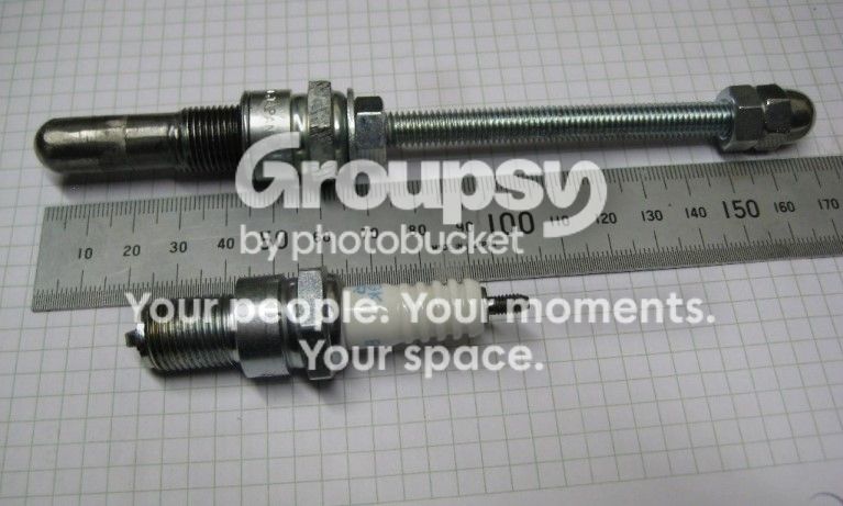
However, use half of you TDC tool to create yourself a dead-stop.  Whip out the hexagonal central sliding bit and replace it with a length of M6 studding, using a lock nut each end to fix it in place. Round the end of the studding that will touch the piston. Simples.

Paul.
 
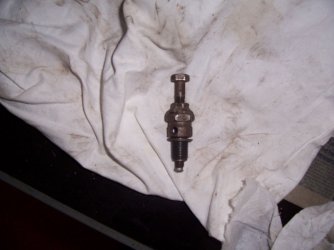
I use a degree disc and stop as my preferred method - this modded spark plug has served me well over the last 30 years - I've pressed in an aluminium plug in the 8mm bolt to avoid any chance of piston damage  - my 12mm stop has an aluminium bolt in it - Regards - Phil
 

Attachments

  • tdc finder.jpg
    tdc finder.jpg
    113.9 KB · Views: 84
this stops the piston at about 50? BTDC.  piss easy to make using a bit of M8 threaded rod, and some nuts.  ,, & a file.
063-pistonstopb.jpg
 
G'day Cam : )

Thank you for keeping a watchful eye on my efforts !

The gismo I have ordered is similar to a TDC stop. It has a 14mm thread so is fitted into the spark plug port and there is a plunger with graduations marked on it so that I can see where TDC commences, dwells and then the point at which the piston begins to descend in the cylinder.

My cunning plan is to use this and also ( at set up stage ) to make a TDC mark at beginning of tdc using a pointy pencil on the back plate against the original crank case mark. Then to observe the dwell and make a second mark just prior to piston going back down. I am hoping the mid point between these two marks will be the centre of TDC and all will be good.

I have read of the other method of bringing the piston up to a TDC stop..reading a degree disc and then reversing the rotation until the piston stops again and re reading the degree disc and halving the reading to find TDC.

all good fun and the learning curve is steep : )

joe

This is the same tool/process I recently used !  clearly in error, so I'm reading the feedback with interest!  :D :D
 
Maybe I'm just really thick this morning, but...  to have your fixed stop mean anything, don't you still need a precise calculation to figure out the crank angle that a specific fixed stop creates?  So you still need to know where TDC is, and then work backwards?  What am I missing?
 
I'm just waiting for someone to mention a fag paper---------------------dam I just did. :D

                                                                                              Dave
 
Rotate crank in both directions to the stop.
TDC lies exactly halfway between the 2 extremes.
Best with timing disc wheel too.
 
beauchemin said:
Maybe I'm just really thick this morning, but...   to have your fixed stop mean anything, don't you still need a precise calculation to figure out the crank angle that a specific fixed stop creates?  So you still need to know where TDC is, and then work backwards?  What am I missing?

The piston stop is set to touch the piston crown just short of TDC. Then the crank is rotated opposite direction and it will stop the piston at the point where it just starts to descend in the cylinder. TDC is in the middle of these two readings and the best way to read is with a degree disc fixed to the end of the crankshaft with a pointer to indicate the degrees turned.

joe
 
Once you've marked the two stopping points on your rotor I find a good way to find TDC is to hold a piece of paper around the curvature of the rotor and mark the two points on the paper. Carefully cut out the strip of paper between the two points and then fold the paper  exactly in half. Put the strip of paper back between the two points and the fold in the paper will show you where TDC is.
 
I also put a mark on the alternator rotor corresponding to max advance to make a quick strobe confirmation easy.  

Once I've confirmed my accurate TDC using the positive stop/degree wheel method I measure the alternator rotor diameter, multiply by pi to get circumference, then divide by 360 and multiply by 32 to get a circumferential distance equating to 32deg advance.
Using a 6 inch steel rule that is quite easy to bend around the rotor I then mark the max advance point.  This is the MOST important ignition timing check you can do, especially with multi-curve or fully programmable ignitions where an incorrect data input could easily toast an engine.  This is quite easy to do within a 1-2 degree precision - sufficient for this procedure which is mainly a "double check".
Cheers
SteveB

Edit: typos and added last sentence.
 
I think I did it graphically,I draw a circle the dia of the flywheel on paper and marked an angle of 32deg from the centre to the circumference that scribed the distance I wanted and marked the flywheel.
 
Back
Top