RGS, DMC and how to make work the rev counter

laves

Full member
hi there,

does anybody know how to make work the RGS - Autobianchi rev counter when bike has been DMC modified?
i would very much appreciate if somebody can give me the necessary insight and instructions and do hope i can execute with my minimalistic level of electrical / electronics knowledge...

many thanks in advance

eric

PS RGS - serial number 1121 - is stock 1982, apart from DMC no other electrical mods (ie standard loom)
 
What is the tacho doing? If it's just waving around all over the place then maybe the counter weights on the needle have fallen off. That's what happened to mine, twice now.

 
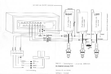
This shows how the damper supplied with the DMC fits.... easy.. even I fitted it.

Andrew
 

Attachments

  • Revised wiring diagram 1.jpg
    Revised wiring diagram 1.jpg
    51 KB · Views: 103
Many thanks
the filter was not delivered in my DMC kit
so i will get one build according to the schema drikko posted earlier in another topic
see attached

drikko said:
Awesome, BTW I just went and checked out mine and it's green, brown and black, different again! The cap is on the green wire side of the resistor according to my capacitor measuring thingy so that's all correct. So if you don't want to buy a filter and want to make one it's:-

coil--------22k resistor----.--------tach green in my case
brown in      1/4W          |
my case                        |
                                    |
                                  = .1 uF cap greencap or ceramic is fine
                                    |
                                    |
                                    |
                                GND
                                black

Uwe Witt was quite happy to tell me what it was!

After that will mount it according to Andrew's drawing
Andrew can you send me a higher definition scan please?

Eric
 
Sorry Eric... it was given to me by another forum member and it's all I have. I could mail you my copy directly if you think it would help.

Andrew
 
BTW there's something wrong with that wiring diagram as it shows 3 pickups but only 3/4 wires going to them, it should be 6, 3 of which are grounded. And the orange wire from the "LEFT" coil on the right of the drawing goes to the orange wires of the other 2 coils. As far as the filter goes, that's fine but it doesn't matter which coil it goes to. The drawing has it going to the centre coil but it can go to any one of them as long as it's the "-" terminal on any coil.


Back
Top