RGS wiring loom connectors

murphus

Senior member
Anyone know where I might find the correct connector blocks for the front wiring loom to main loom on an 84 RGS? Started disassembling the 84 RGS for a frame refreshening and discovered the previous owner decided, for reasons unknown, to super glue the connector blocks together. Seriously. In the event they don't come apart without destruction, I'm looking for options. Yeah, I can just rewire, but I'd like to keep it stock. I have a spare main loom and had a spare front loom, but passed the front loom along to another RGS owner who needed it last year.
Richard
 
look for suppliers of Honda or Suzuki parts of that aera:

https://www.haralds-oldieshop.de/collections/suzuki-1/zubehor-kabelbaum

not sure he delivers to your part of the world, but maybe similar shops there around?
 
Rob said:
You may be able to...in the UK is a company called Kojaycat.  If you send 'em a photo - maybe with a ruler in shot - they likely will be able to help.  https://kojaycat.co.uk/
As Lothar says, there doubtless are others

I have got the correct stuff from these guys for my S2 Jota and a 1985 MHR Duc.
They also have a good range of crimping tools etc.
 
If you're in the US, try Cycle Terminal, they also have the correct thing.  You're after non-locking 0.110 connectors, down the page here:
http://www.cycleterminal.com/110-connectors.html

Also, if it's only because the plastic housings have been glued together (what some people do boggles the mind), you can possibly just cut/dremel/etc the plastic bits away and leave the terminals intact, meaning you only need to fit new housings.  I'd still buy the terminals just in case, but you may not need to re-terminate everything.

When purchasing, don't forget to buy the terminal extraction tools as well.  Basically just a flat spike, but just the right shape and material to do the job cleanly.
http://www.cycleterminal.com/crimp-tools.html
 
Excellent! Thanks for that, exactly the stuff, and turns out I couldn't order from the UK if I wanted to, no international orders are being processes. Already have a terminal tool, but thanks for the tip.
Richard
 
Digikey have just about every type of connector known to man. In fact there are so many options that'll take a while to filter through to what you need...
 
breganzane said:
If you're in the US, try Cycle Terminal, they also have the correct thing.  You're after non-locking 0.110 connectors, down the page here:
http://www.cycleterminal.com/110-connectors.html

That's a super useful site, Steve. Knowing what to get would be the biggest prob!
 
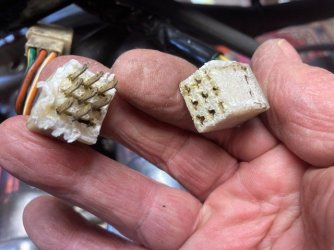
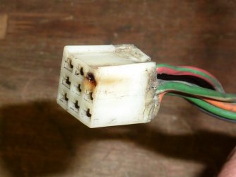
An update to this thread. Pics of the connectors. I had to break them apart. They really did seem glued together, but I'm wondering if there's another reason for why they fused together? Some sort of assembly grease gone bad? The electrical contacts themselves are in fine condition.
 

Attachments

  • C1.JPG
    C1.JPG
    61.6 KB · Views: 28
  • C2.JPG
    C2.JPG
    72.3 KB · Views: 26
These connectors often overheat, making it close to impossible to seperate them after they have melted. Makes sense to re-route charging and headlamp current through relays, the new connectors and the handlebar switches will be glad.

piet
 
 
Hadn't thought about overheating, Piet, that makes the most sense. I installed relays on the 83, will do the same again. MotoJouni, thanks for the link, already sourced the proper connectors through cycleterminal.com but good to know.
 
Sadly no assembly - or dielectric - grease was applied by the factory. As Piet says, the issue is overheating. Those small contacts are on the limit for the alternator loop that runs from the alternator phase winding, up to the headlight switch and back again. Throw in some muck from the front wheel and heat from the engine for a gentle meltdown!

The green/white and green/red wires on the handlebar switch side of the connector (plus their mates on t'other side) carry the full output of one alternator phase with the headlight on ... which I guess is all the time for you? If so, you could bypass that loop and connect the alternator green/white direct to the reg/rect red/white via the bullet connectors behind the airbox. I think the factory wired one alternator phase through the light switch to avoid overloading the original ND reg/rect. Not an issue if you always ride with the headlight on, although another excellent idea would be to replace the OE reg/rect before it fails and possibly takes out your battery too through overcharging. Well past its 'use by' date after all these years.

Headlight relays also a good idea.
 

Attachments

  • melted.jpg
    melted.jpg
    87.6 KB · Views: 4
so what happens to the output of the 3rd charging coil when the lights are off? (yes, I'm electrically illiterate..)

and what else would benefit from relays? I've already stuck them on the headlight, where they made a massive difference.
 
o what happens to the output of the 3rd charging coil when the lights are off?
It goes nowhere - the output is open circuit until the headlight is switched on. It then joins the other two phases at the reg/rect to make the full output from the alternator available.
what else would benefit from relays
The main supply feed through the ignition switch to the fusebox

There is an argument that increasing the component count and/or connections increases the risk of failure. Against that is volt drop across aging switch contacts. Your choice! You could get clever and arrange to wire the relay in parallel with the ignition switch to minimise single point of failure risk, but would need a diode to ensure it denergises when the ignition switch is turned off
 
It goes nowhere - the output is open circuit until the headlight is switched on. It then joins the other two phases at the reg/rect to make the full output from the alternator available.
Thanks. Think I'd better do some reading, I'm contemplating changing the switches on the SFC (never liked those ND switches) but I'd best figure out what do with the 3rd phase...

Hmmm, if it's open circuit does that mean less drag on the crank as it's generating less electricity? Maybe being a electrical numpty is going to have to change
The main supply feed through the ignition switch to the fusebox

There is an argument that increasing the component count and/or connections increases the risk of failure. Against that is volt drop across aging switch contacts. Your choice! You could get clever and arrange to wire the relay in parallel with the ignition switch to minimise single point of failure risk, but would need a diode to ensure it denergises when the ignition switch is turned off
oh yes, I can see that taking the full fat 12v out of a 30+ year old ignition barrel is a good thing and, well. voltage drop - when I did the relays for the headlight the light was only getting 5v when fed through the old switch.
 
Back
Top