SF2 Starter Button Assembly

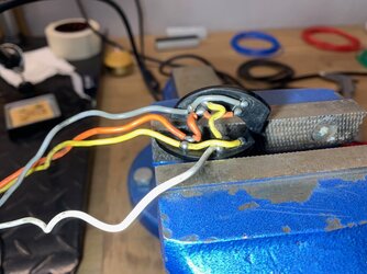
Anyone have a pic or description of how the yellow and green wire attaches. Mine quit working so pulled it apart and the spring is permanently deformed and green/ Yellow wire unattached. Been so long since I was in there I forgot where it goes. Is it a washer engaging spring in button ?
Cheers
 
OK , I have got :

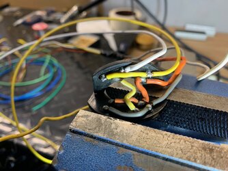
There is an orange wire , carrying "juice" to the kill switch.
From there it splits in two orange/white wires.
One of those goes to the ignition coils
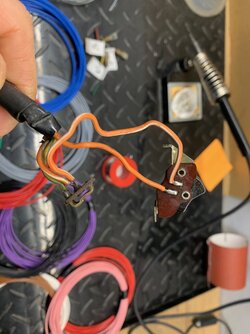
One goes to the starter button. From the starter button it goes to the starter relais through the green/yellow wire.
So pushing the starter button sends a current to the starter motor, which has an earth cable.
It's a Micky Mouse switch , like the LH block...
Hope that helps
 
Thank
OK , I have got :

There is an orange wire , carrying "juice" to the kill switch.
From there it splits in two orange/white wires.
One of those goes to the ignition coils
One goes to the starter button. From the starter button it goes to the starter relais through the green/yellow wire.
So pushing the starter button sends a current to the starter motor, which has an earth cable.
It's a Micky Mouse switch , like the LH block...
Hope that helps
Thank you. I have the schematic and can see yellow/ green heads off to solenoid. It is detached in my switch and I cannot see how it attaches. I assume to the spring or pin in the starter button so when pressed it takes the live feed from the orange wires soldered to the board, but cannot figure how it is attached. Maybe a soldered to a small washer behind spring?
 
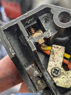
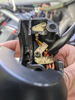
Yellow/green soldered onto that brass tab seen here. Orange/white soldered onto the insulated board to be contacted by the pushbutton shaft. Fiddley.
 

Attachments

  • PXL_20210925_022656550.jpg
    PXL_20210925_022656550.jpg
    184.6 KB · Views: 25
Ch

Cheers. Trying to figure the way the yellow / green attaches to starter button to complete the circuit
Yellow/green soldered onto that brass tab seen here. Orange/white soldered onto the insulated board to be contacted by the pushbutton shaft. Then, 2nd pic, covered over with plate and screwed down.
Fiddley.

Attachments​

  • PXL_20210925_022656550.jpg
    PXL_20210925_022656550.jpg
    184.6 KB · Views: 0
 

Attachments

  • PXL_20210925_024156563.jpg
    PXL_20210925_024156563.jpg
    115.6 KB · Views: 13
Last edited:
Nice clear pics. On this topic 9sort of) I bought a 'replica' ND RH switchblock and while the casing looks great, I was getting intermittent failure to transmit electricity from both the on-off toggle and the starter button. Looked perfect but just crap quality, so I fitted the toggle and button assembly that came from a genuine ND I had in my spares bits and pieces - always pays f=to hang on to those little 'irrelevant' parts!
 
Back
Top