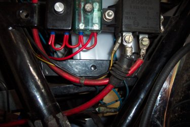
Size of the wire from +ve terminal to the starter relay.

Simon Yates

Senior member
Managed to get a spark today on my 1969 750 refurb, but, in the process, the insulation on the existing wire from battery +ve  to one of the large terminals on the starter relay melted.  Does it need to be the same CSA as the relay to the starter? If not, what size should it be?
 
Does it need to be the same CSA as the relay to the starter? 

they both (batt-relay & relay - S/motor) need to be heavy duty cable - most car accessory shops will sell it. - Regards - Phil
 

Attachments

  • 102_1822.JPG
    102_1822.JPG
    181.7 KB · Views: 37
16mm2 multi strand extra flexible battery lead is what you're after ... plus decently crimped lugs with a 6mm hole.  As Phil says, required for the complete run from battery to relay and relay to starter.  You also need the same size for the return path to battery negative (I'll refrain from calling it ground and await arguments saying it's the forward path.... >:D )
 
Battery to Solenoid and Solenoid to Starter 00 Gauge (4 will do) with clean connections. Starter switch circuit from battery through key to solenoid and grounded through tranny neutral switch 14 gauge.
 
Simon Yates said:
Unlike me - I am of a mechanical persuasion. :-X
I think my posts suggest this.
I am a clanky too Simon!
My electrical buddies at work rather tiresomely correct me many times.
Apparently wires are a single strand of a cable and bulbs grow in the earth  :D
 
I find it quite strange that a many people with mechanical know-how are utterly boggled by electricity. It's really very simple and logical. If you think of it as analogous to hydraulics you shouldn't go too far wrong. Big current = big pipe, etc.
Sometimes I feel like slapping guys on the back of the head when they ask stupid electrical questions.  ::)
 
Cam,

Everywhere I have worked there is quite a rivalry between the Instrument, Electrical and Mechanical trades.
basically they all think they are the best and the rest are numpty's.

Are you sure big current = big pipe?
When we transmit electricity over long distances we step voltage up quite a bit to 400,000 Volts, so that is 'big pipe = big pressure (volts) and small flow rate (current) and thus low losses in transmission.

 
SimonR501 said:
Cam,

Everywhere I have worked there is quite a rivalry between the Instrument, Electrical and Mechanical trades.
basically they all think they are the best and the rest are numpty's.

Are you sure big current = big pipe?
When we transmit electricity over long distances we step voltage up quite a bit to 400,000 Volts, so that is 'big pipe = big pressure (volts) and small flow rate (current) and thus low losses in transmission.

I'm with Cam on this one. Current shouldn't be confused with power.

cheers,

bazzee
 
As long as I am not responsible for initiating a civil disagreement at this moment.
There will be plenty of other opportunities I am sure.
 
SimonR501 said:
Are you sure big current = big pipe?

Absolutely sure.

Think of spark plug wires. The voltage is very high (tens of thousands of volts) so the insulation is thick to contain the voltage (pressure) but the wire conductor is quite skinny because the current (flow rate) is miniscule, typically a small fraction of an amp.

For a more extensive hydraulic analogy of electrical parametrs:
Current = volume rate of flow (litres per second, CFM, whatever)
Voltage = pressure or static head
Resistance = friction in pipe or other appliance.
Generator = pump
Motor = turbine or impellor
Pipe wall thickness = insulation thickness
capacitor = rubber diaphragm
Coil = er ... dunno, I'll have to think about that. I suppose it's equivalent to a master/slave cylinder arrangement.

OK, the electrical purists will cry out that the analogy doesn't hold up under any kind of close scrutiny, but what analogy does? It's good enough for beginners to come to grips with basic electrics in simple circuits like we have in old motorcycles and cars. Modern vehicles are getting away from simple circuit electrics because of all the computers and semiconductor crap everywhere.

When we transmit electricity over long distances we step voltage up quite a bit to 400,000 Volts, so that is 'big pipe = big pressure (volts) and small flow rate (current) and thus low losses in transmission.

The reason the voltage is stepped up for transmission lines is (as you say) to reduce the current, so smaller conductor can be used, thus reducing cost. Otherwise you would need massive wires that would be ridiculously uneconomical. The wires are still pretty big because EHV transmission lines typically carry a lot of power. The larger the conductor the lower the resistance, so it's a balance between installation cost and power loss.

In a previous life I used to build EHV transmission lines and substations. It was interesting work, especially for a mechanical engineer such as myself.

 
In a previous life I had to give trainee submariners a basic understanding of the electrical systems on a boat; diesel generators, 8400 amp-hour main storage batteries, battery charging, main propulsion and so on. to get the message across, even to stokers, I used the analogy Cam mentioned. It was good to see the lights going on around the classroom as the penny dropped.
 
Dellortoman said:
The reason the voltage is stepped up for transmission lines is (as you say) to reduce the current, so smaller conductor can be used, thus reducing cost.

(bigthumb) I think this where many get confused.
 
Back
Top