Valve Adjustment After Head Removal-RGS1000SFC

Rockitdoc said:
I understand the shims come in 0.07 mm increments, so it is not possible to get all three clearances exactly the same, right?  Or, am I missing something.....as usual.

With a bit of practice/experience, it is...

My box of shims has increments of all sorts, usually end up within 0.02-0.03mm of one another.

piet
 
G'day Doc

You can also rub the shims down on an oilstone for fine adjustment. Keep rotating them as you do it so as not to grind them unevenly.

I have a pdf copy of the workshop manual but it's too big to post here or send as an email attachment. I downloaded it from the web somewhere, so it's probably still out there. If you prefer a real one there are a couple on ebay.

Cam
 
Dellortoman said:
G'day Doc

You can also rub the shims down on an oilstone for fine adjustment. Keep rotating them as you do it so as not to grind them unevenly.

I have a pdf copy of the workshop manual but it's too big to post here or send as an email attachment. I downloaded it from the web somewhere, so it's probably still out there. If you prefer a real one there are a couple on ebay.

Cam

I've got a pdf but it is hard to read.  Maybe I'll look for an ebay version.

 
As already stated, you will struggle needlessly to get these clearances 'spot on'.  I aim for .20 inlet .25 exhaust and then settle for something between that and the upper tolerance. Within reason, slack is better than tight
 
Hi Doc

firstly. Wolfgang has a big supply of both new and used shims. If he happens to be away, I bought a supply from him a while ago, I have between 3 to 5 shims in pretty much each size available. If you get desperate pm or email me.

you obviously have figured out how to time the cams and put the cam chain together, as you have the head back on. So, adjusting the valve clearances will be easy for you.

first, start the bike as it is, and if it is rideable, take it for a good ride. Bring it back, let it cool down, re torque the head.

then measure valve clearances on each valve, write the clearance down.

then split the cam chain and take the cams out.

pull the first valve spring bucket, you already know its running clearance, and remove the shim. Measure the shim carefully, from its flat top to the inner recess is what you are measuring. You will need a micrometer or similar. Once you know the shim thickness, do the math to calculate what shim thickness you actually will need. Number the bucket, and toss the shim into it for now, and remove and measure all the rest, and do your maths.

if you had the head off to have valve seats done, or new valves or guides, I would set the valve clearances on the loose side to give you some working room for the valve clearances to close up as things settle in.

a looser clearance is always better than a tighter clearance. Clearances will never get looser, they will always get tighter with valve seat and valve stem wear.

to keep track of everything, use a basic worksheet. Steve B did a decent one a few years ago and it is still available for download.
http://www.breganzane.com/workshop/valves.php

then put the new proper sized shim under each bucket as required, re assemble, turn the engine over a few times, and re check clearances just to be sure you did your maths correctly......

just be methodical, use an accurate measuring device, and don't sweat .02 or .03 clearance differences, they are pretty much inevitable. If I had one exhaust valve at 0.25 and another at 0.30, I wouldn't pull the cams to change that, as an example. If I had one at 0.25 and another at 0.15, I would pull the cams....

Paul LeClair
 
Dellortoman said:
You can also rub the shims down on an oilstone for fine adjustment. Keep rotating them as you do it so as not to grind them unevenly.

Just as an aside, are the shims hardened throughout? Or surface hardened?
My guess is surface hardened, so if you take a lot of material off then put that side downwards.
Just have to remember when it comes out.
 
Paul LeClair said:
Hi Doc

firstly. Wolfgang has a big supply of both new and used shims. If he happens to be away, I bought a supply from him a while ago, I have between 3 to 5 shims in pretty much each size available. If you get desperate pm or email me.


Paul LeClair

thanks paul for the offer.
I got hold of wolfie and he is sending the shims I should need if I did the numbers correctly and if I read my mic correctly.  big IF.  timing the thing is the next step after cams go back in. I downloaded one of the degree wheels from the site so I could see what my intake and exhaust degree readings are.  not sure I will go to the trouble of doing adjustments unless the readings are really off by a lot.  one thing I could use though is confirmation of the degrees of intake and exhaust for the F1A cam.  my info says 30 and 50 and 50 and 30 for intake and exhaust open and closed, respectively, but not sure this is correct.

 
damn difficult getting exact opening and closing points on a camshaft, you are better off working out lobe center at TDC
on a SFC 1000 cam lobe center is set at 100 degrees on both camshafts

 
redax5 said:
damn difficult getting exact opening and closing points on a camshaft, you are better off working out lobe center at TDC
on a SFC 1000 cam lobe center is set at 100 degrees on both camshafts
Thanks Red.  Now I understand what the book meant by '100 degrees max'.  That will be easy to measure. 
 
Rockitdoc said:
That will be easy to measure.

has stumped a lot of people in the past so am looking forward to seeing how you go

to get truely accurate measurements you need your dial gauge reading off the cam follower

 
redax5 said:
has stumped a lot of people in the past so am looking forward to seeing how you go

to get truely accurate measurements you need your dial gauge reading off the cam follower

Should just be able to mount the dial gauge above the bucket (the bit the cam pushes on) and measure when it reaches the bottom of it's travel.  Right?  That would be when the cam lobe is acting directly downward on the bucket.  What am I missing?
 
Doc, it's a bit like determining TDC. You can't accurately measure the crank angle at maximum valve lift (lobe centre) because you can turn the crank a few degrees either way from lobe centre with bugger-all change in valve lift. Best way to do it is to record the crank angles (from your degree wheel) at equal lift before and after maximum lift, and split the difference to get lobe centre angle.

While on the subject, you need a piston stop to find TDC and zero your degree wheel using a similar method as described above. Don't rely on the mark on the alternator. They're generally OK, but if the alternator rotor has been changed, or the keyway worn, it might be a bit off.

Edit:
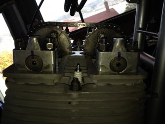
I've just been doing the same job myself. My camshaft sprockets have been modified, so the timing marks are useless. Having forgotten to make some marks in the right spot before I took it apart, I had to re-set the cam timing with a degree wheel and dial gauge on a cam follower. After getting it set up correctly, I made a couple of marks with a permanent marker across the ends of the camshafts and onto the bearing blocks, just to see if it would be useful on such a small diameter. As it turns out, it is. One tooth out on the sprocket is quite obvious.

It makes it dead easy when doing shims to get the camshafts back in the right position because you're working from the right side of the bike (where the nut is to turn the crankshaft) so don't have to wander around the other side to look at the marks on the sprockets.

I reckon I'll make some permanent marks with a Dremel. Might make a TDC pointer for the Redax alternator while I'm at it too. Should make life easier next time I'm doing shims or ignition timing.
 

Attachments

  • cam timing marks.jpg
    cam timing marks.jpg
    186.1 KB · Views: 32
Back
Top