Worn crank end

Dellortoman

Hero member
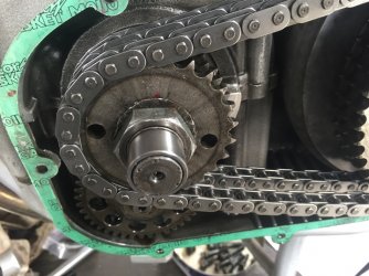
Had a simple job to do today - replace a crankshaft outrigger bearing on a mate's Jota. I presume it was making a noise last time he had it running (I haven't been able to start the engine yet for reasons unrelated to the bearing).  Anyway, I have a replacement bearing and the pullers necessary to remove the inner and outer bearings, so figured it would be a quick job ?  Wrong  :(

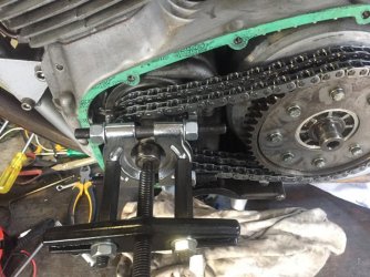
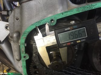
Found the inner race was loose on the end of the crankshaft. I could spin it and rattle it about with my fingers, but couldn't pull it off with my fingers because of the peening on the end of the shaft. The bearing puller got it off with no trouble. The old inner race had apparently been spinning on the shaft for long enough to wear it down.  I took a bunch of measurements and the diameter is between 19.58 and 19.63 (digital caliper moved a bit when I took the photo). So an average of around 19.60, which is 0.4mm down from the original 20mm.

I'm intending to use some Loctite 660 to fill the gap between the crank end and inner bearing race. The blurb says it's OK for gaps up to 0.5mm. While the crank end is undersize, it's still cylindrical (not worn oval or tapered) so I figured I'd use 3 or 4 narrow strips of 0.2mm brass shim (laid axially along the shaft) to keep the bearing centred and aligned while the Loctite cures. Can anyone foresee a problem with that approach?


PS: Piet might be interested to note that there are spring washers under the bolt heads on the clutch (referring to his post on another thread today). There's no evidence of them touching the webs on the inside of the primary cover so perhaps the aftermarket primary cover gasket is a bit thicker than the original.
 

Attachments

  • Worn crank end.JPG
    Worn crank end.JPG
    114.7 KB · Views: 71
  • puller.JPG
    puller.JPG
    144.6 KB · Views: 86
Cam,

An easy fix is to source an inner race with smaller ID (24 x 17 x 20 is readily available) and machine that to size.  With the correct tools, bearing steel machines surprisingly well.  Done this several times to rescue an otherwise usable shaft, alot easier than welding, grinding, etc...

Before you proceed, make sure the journal runs true, just a little run-out can cause the race to loosen again and find its way to daylight.  Please also be aware that the OD will increase dramatically if too much interference fit is used.

Once came across a clutch that had been modded with allen screws and lock washers, made a not-too-pretty interuption in the reinforcing webs of the cover.  Better not to have much end-float on that basket with lock washers! :D

piet
 
Thanks Piet. I hadn't thought of getting an inner race with undersized ID and machining it to suit the reduced crank diameter. I would have thought the bearing steel all but impossible to machine.

I have a boring bar that'll go into 17mm hole, but it only takes HSS cutting tools. Perhaps this is a good excuse to buy one that'll take tungsten carbide tips.

 
sfcpiet said:
Once came across a clutch that had been modded with allen screws and lock washers, made a not-too-pretty interuption in the reinforcing webs of the cover.  Better not to have much end-float on that basket with lock washers! :D

seen same primary cover damage on a couple of engines
I use Button head bolts with Schnoor serrated lock washers, plenty of clearance
 
Dellortoman said:
I've not tried machining bearing races before. Does anyone have any handy hints?

Slow bites and slow drive Cam, I had to take 2.5mm off a hardened bearing race ... took lots of beer and and coolant. Had my doubts, but it worked.
 
Do you have a collet chuck Cam?  A regular 3- or 4-jaw chuck will distort the ring and you'll end up with a triangle or square... not to mention the lack of precision these chucks often have.

Tungsten carbide tip works fine.  Shallow cuts with slow feed, but not too slowcutting speed, otherwise the tool will chatter.  The ring has enough material for a bit of experimenting.

piet
 
Thank for the tips guys

No, I don't have a collet chuck.

My plan was to turn up a 4-segment "collet" from a lump of aluminium bar, put it in the 4-jaw chuck, bore it to a tight(ish) fit on the OD of the bearing ring. Press the ring in and tweak each jaw up to hold it tight. I suppose that's a cross between a collet chuck and a set of soft jaws. If it goes a bit off-centre after tightening the jaws, at least I can re-centre it with the 4-jaw.

What could possibly go wrong? I suppose the worst that could happen is I'll fuck up a $30 bearing ring.

I've been doing a bit of research on hard turning and it all seems do-able. But I'll need to acquire a suitably sized boring bar that'll accept tungsten carbide or CBN tips. I haven't checked prices of tooling yet. Might turn out to be horribly costly for a one-off job.

Before doing anything, I'll go and have a chat with a mate who manages a general engineering workshop. If he reckons I'm biting off more than I can chew with my soft jaw idea and limited machining experience, I'll get him to do it.
 
Soft jaws will be fine Cam.

If you can set up a larger gripping area at each jaw, that will prevent distortion to a large degree.

You won't regret buying a suitable boring bar, carbide tips are good for all sorts of stuff.

Wondering about your $30 quote, sounds rather ott.  :o They cost around ?10 here.
piet
 
Yeah. Local bearing shop quoted $30, which I thought was a bit rich too. But I can't find a cheaper source here in Tasmania.

As you say, they're available on line for around ?10, but all the sellers I've found are overseas and postage to Tasmania makes them around $30(Aus) or more anyway. So I may as well go with the local bearing shop.
 
Cam! You could always turn up a thick-walled ring that is size for size of the outer diameter, then cut right through it.
With any luck, once cut the ring will spring apart slightly.
You then have a custom holder for your bearing that will clamp it beautifully in a regular 3 or 4 jaw chuck without distortion.
4 jaw is better because you can eliminate runout.

Keep the boring bar as short as possible in the tool holder. If your boring bar 'sings' then change speed and feed.
 
FFF    >:(
Bearing supplier now reckons he can't find a 17x24x20 inner bearing ring anywhere in Australia, so I've had to order from UK. Cost worked out about the same but half of that was postage. Since the cost of the actual bearing was only about $15, I ordered two so I can have a second attempt it if I cock it up the first time.
 
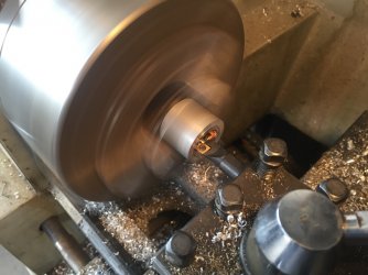
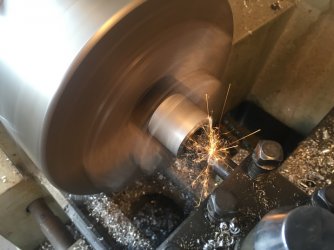
Bearing ring finally arrived from UK. It wasn't such a bugger to machine as I had expected. I just had to get used to the red-hot swarf and sparks flying!

To centre it in the chuck I just made a holder out of a scrap of 30mm diameter alloy bar. Bored a 22mm dia hole through it then bored a 24mm dia recess in one end, 16mm deep. I made the 24mm bore size sop the bearing ring was a press fit. Without removing the alloy holder from the chuck (so as to preserve the centre) I tapped the bearing home in the holder (that's the reason for the 22mm through hole). I was then able to cut it down to the desired 16mm length by machining the end with a tungsten tip until it was flush with the end of the alloy bar (that's the reason for the 16mm deep recess). Once the length was right, I used a tungsten tipped boring bar to take the bore out to 19.5 (ish) mm to fit the worn down shaft. I actually tapped it out of its holder and trial fitted it about a dozen times, taking a thou off each time until it was a nice press fit on the shaft. Leaving the alloy bearing holder in the chuck meant the bearing ring would still be centred when put back in the holder for another skim of the bore. 

One minor hiccup was that the 16 x 24 x 20 bearing ring was a very tight fit in the needle roller. By "tight" I mean an interference fit. The only way it would go in was to press it in. Once in there the bearing was so tight it was difficult to turn. To get it out again I had to tap it with a drift. Bugger!

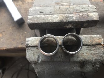
When the ring was pressed onto the shaft, the OD increased due to the stretch over the interference fit, and there was no way the needle roller bearing would fit over it. So I had to relieve the clearance for the rollers by taking a bee's dick off the OD of the ring. I did that by making a little stub shaft to hold the bearing ring in the lathe, then used fine emery cloth wrapped around a piece of flat bar as a kind of makeshift file while spinning it at high revs. It took forever but I managed to polish a thou or two off the OD so that it was a nice sliding fit in the bearing, without being loose. The bearing surface was still nice and shiny so it should be OK.

Not being confident that I'd get it right first go, I actually bought two bearing rings (16 x 24 x 20 - ID x OD x L) so if I stuffed up the first attempt I could have a second try. I didn't use the second ring. If anybody needs it for a similar job, you're welcome to it for the cost of postage and maybe a small donation to the shed fund.
 

Attachments

  • red hot.JPG
    red hot.JPG
    132.8 KB · Views: 28
  • sparx.JPG
    sparx.JPG
    126.8 KB · Views: 30
  • rings.JPG
    rings.JPG
    157 KB · Views: 25
  • job done.JPG
    job done.JPG
    181.1 KB · Views: 32
Good work Cam. Didn't need the emergency, so job well done. Hopefully the hardening is more than those few thou thick. ot easy predicting the expansion of the ring when fitted to the shaft and not something you want to fit and remove!

My stock of boring tools is too limited and I often have trouble getting a good finish. Might have ot invest in one of those smallet carbide numbers.
 
Back
Top