SFC COVER

I wasn't winging about moddern tech. doing away with my job etc. I wish I had that stuff in the 70,80,90s when everything was done by hand.
Mid 90s when working in Hong Kong we brought Swiss made plotting machine with a bed od 1200x900 with a router type motor that ran up to 30000rpm.. A couple of us got trained to to use the German developed software percifcally for modelmaking. We had milling cutters as small as 0.4mm. Also had a cutting head with a tungsten blade that could cut masking. What a revelation that was. The Guys I work with in Sydney now have 3d printers and rapid prototyping and some of the stuff they're producing blows me away. Still glad I got out of it back in 2006.

I'm amazed how your using 3d printing for proto types. Wish I had one when scratch building the Motodd.
 
Lots of good points there Todd,
I just dont get excited over computers spitting out bit of plastic thats all.
Pretty simple really.
I hope it goes well and the side cover comes out perfect.
As with everything, theres always more than one way to skin a watermelon.
Cheers
Tom
 
We used a big 3D printer for making prototype parts for the combine harvesters - one of the things I didnt quite understand is the following question - do you need a cad drawing of the part to make one ? While I know all the combine parts are designed on a form of cad - how did you get the pattern for the side cover into the printer ? What have I missed ?
 
We used a big 3D printer for making prototype parts for the combine harvesters - one of the things I didnt quite understand is the following question - do you need a cad drawing of the part to make one ? While I know all the combine parts are designed on a form of cad - how did you get the pattern for the side cover into the printer ? What have I missed ?
Good question, Sir Sid. I'm wondering whether there's some sort of scanner that can record the coordinates in 3d from different angles and then plot it all together. to create the CAD info. But I know jackshit about it!
 
We used a big 3D printer for making prototype parts for the combine harvesters - one of the things I didnt quite understand is the following question - do you need a cad drawing of the part to make one ? While I know all the combine parts are designed on a form of cad - how did you get the pattern for the side cover into the printer ? What have I missed ?
The 2D drawing isn't required. The printer (or any CNC manufacturing device) takes the 3D data direct from the CAD model.

Where they are required, quite a lot of 2D drawings these days have a few basic views and the note 'For unspecified dimensions, see 3D data'. Sometime with a few dimensions put on them, which are used for quality checking of significant characteristics.
 
Ah but are you saying the engineering drawings for Laverda parts are in an electronic file ?
If you mean old Laverda parts (drawn by a bloke in Breganze with a 'pencil' on a sheet), then this has to be modelled in 3D. A very similar thing to how a pattern or tool maker used to take a fully dimensioned 2D drawing and turn in into a 3D form, the same same is now done, but the result is a 3D 'solid' electronic model is made. The CNC device can understand this 3D model and lay-down material, or cut material, accordingly.
 
We used a big 3D printer for making prototype parts for the combine harvesters - one of the things I didnt quite understand is the following question - do you need a cad drawing of the part to make one ? While I know all the combine parts are designed on a form of cad - how did you get the pattern for the side cover into the printer ? What have I missed ?
You have what they call a "slicer" which is software, that takes the file that the part you want printed is drawn in, be it a .dwg .step or .obj etc
and it slices it into all the layers that the printer prints, it turns the drawing into G code, which is the language most printers speak. G code
gets sent to the printer and the printer then prints from that information
The sort of printer you see photos of items printed on this forum, basically draws layers and layers of melted plastic on top of each other. The slicer basically slices your drawing file into each layer and tells the printer what to do at any given time of the print. the slicing software works on the same principle on most 3 d printers if they are printing in metal powder or plastic powder or plastic filament etc powder printers ( SDS printers) sinter ( melt the powder with a laser) the material in layers to build up your object
 
Good question, Sir Sid. I'm wondering whether there's some sort of scanner that can record the coordinates in 3d from different angles and then plot it all together. to create the CAD info. But I know jackshit about it!
There is, but they arent good for little items, complete car fenders or panels etc yes , small objects dont work out so well . A simple scanner costs about 60K euros, and is great if you are scanning biggish objects, but so far scanning little objects, the file comes out quite loew resolution, so before you print that object you need to clean the file up in in some form of drawing software. A while back I scanned my alternator cover with the above 60K scanner, and it was quicker in the end to draw a new model rather than clean up the 3 d scanned file.
 
Cross post - but will post anyway....

Sid - If you have a part you want to replicate, you can also scan it into 3D. This is good if you don't have the old drawing and even if you do it saves the trouble reading off all the dimensions on the drawing. But when scanning is done you might be replicating errors exisitng in the sample part. You can take a scanned model and tidy it up in 3D CAD though - to make it true and closer to intent. The boundaries in 3D are becoming limitless.
we could then print patina'd scratched and dented parts :unsure: ;) not !
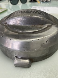
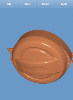
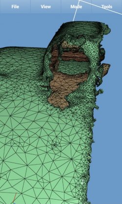
Below are the scan results of the alternator cover, The scanner is good enough to pic up the imperfections, so then you need to fix them in some drawing software... rhino fr fusion 360 etc
photo 1 is the condition my alternator cover was in,
photo 2 after scanning
photo 3 is what you need to clean up all the little lumps and bumps , the round hole that looks like its spewing brown gunge is the breather?/ drain hole on the bottom of the cover

The little triangles you see in photo 3 are representing the 3 d mesh that the scanner lays over the object
 

Attachments

  • IMG_4729.jpeg
    IMG_4729.jpeg
    115.7 KB · Views: 22
  • cfff61b2-723d-4711-b212-b0b599251822.jpg
    cfff61b2-723d-4711-b212-b0b599251822.jpg
    38.7 KB · Views: 21
  • 87358fa9-a7a4-4715-b359-bbbda409f663.jpg
    87358fa9-a7a4-4715-b359-bbbda409f663.jpg
    156.8 KB · Views: 23
Last edited:
Ok now we are getting there - sorry for the dumb questions - so to summarise you can scan an old part - this produces a file that can be cleaned up in a software then fed into the 3D printer to make a plastic or metal part depending on the printer ( the combine one we used made resin ones) - this in turn could be used to make a mould ( sand) to create a final part

I have seen some pictures of a cylinder head from Sweden

long term this could be an answer to some parts
pretty much you've got it! Then you just need to scale the part for printing a smidge so the casting comes out the right size
Im quite keen on casting some magnesium parts
 
No dumb questions Sid - this subject is truly massive. It's interesting to learn the principles, then that expands to a huge world of 3D.
Even for me it is fascinating, and I started my CAD career in 1982. Back then we were in 2D (kinda electronic pencil) then 3D wireframe, then 3D solids, then 3D parameterics, and on and on it goes.

Fannying around with this at the mo....
 
I think it is brilliant! wished that technology had existed 15 years ago when I attempted to reproduce the series 2 alternator covers...

The shifter cover is maybe one of the easiest to do, not to much machining involved afterwards. for the other covers, you will need to encounter additional material for all the things that need machining/drilling etc.
 
It’s good to have some basic understanding 😀

Red went through the procedure before all this I guess for his side covers and really volume is the game here - my cover was cracked when I bought Joan and I guess as long as I regularly operate the clutch and use recommended oil the new one should not crack again I hope !

I have seen the handlebar switches on fb created by 3D printing - indicator / lights on / dip and main between
 
Bought a 3D printer as a Chrissy present to myself, truely amazed at the possibilities, and I'm only starting to getting to grips with it! Being so lazy 30 years ago when I could have learnt all that CAD stuff is now biting me. Learning new stuff is definitely a lot harder these days.

Now I need to upgrade my 'pooter, old one's still running on steam...:rolleyes:

piet
You haven't lost anything Piet, CAD 30 years ago was totally different - not only in what's achievable, but it's also a totally different modelling mind set.

Example; Back then, to draw a 3x4x5 rectangular block you would quite deliberately draw a 3x4x5 block. No surprises there. Today, a lot of systems are different. Firstly, you draw any 6 sided wobbly 'thing' and then start laying rules (parameters) onto the lines/edges/faces to pull it into shape. 'I want you to be 90 degrees to him', ' I want you to be 3 long', 'I want you to always be the same length as him', etc. If you set all the rules correctly, then you can change 1 parameter and all the other elements get pulled into the new shape. So, if you really wanted a 3x4x6 block, you just pick your master 5 long line and tell it to be 6 long now, and everything else jumps to fit.

I have the utmost respect for old school toolmakers/pattern makers/etc. When I stood at the drawing board with a pencil, doing my thing, I often thought, fuck me, that is gonna take some serious skill to make, then some months later you had the metal in your hand. That thing that once only exisited in your head is now real. Amazing.
 
Last edited:
You haven't lost anything Piet, CAD 30 years ago was totally different - not only in what's achievable, but it's also a totally different modelling mind set.

Example; Back then, to draw a 3x4x5 rectangular block you would quite deliberately draw a 3x4x5 block. No surprises there. Today, a lot of systems are different. Firstly, you draw any 6 sided wobbly 'thing' and then start laying rules (parameters) onto the lines/edges/faces to pull it into shape. 'I want you to be 90 degrees to him', ' I want you to be 3 long', 'I want you to always be the same length as him', etc. If you set all the rules correctly, then you can change 1 parameter and all the other elements get pulled into the new shape. So, if you really wanted a 3x4x6 block, you just pick your master 5 long line and tell it to be 6 long now, and everything else jumps to fit.

I have the utmost respect for old school toolmakers/pattern makers/etc. When I stood at the drawing board with a pencil, doing my thing, I often thought, fuck me, that is gonna take some serious skill to make, then some months later you had the metal in your hand. That thing that once only exisited in your head is now real. Amazing.
Yeah, but as I'm close to being a total 'pooter numpty, I find it hard to keep an overview of all the available options, makes my bloody head spin! New computer is ordered and being configured, hopefully my choice of CAD software will work satisfactorily on that. A mate will be instructing me, so hopefully, I'll be up and running soon. Been print practicing with free/shareware objects and slicer, difficult enough for a start...

Sometimes I wish my old drawing board back, used to be quicker on that than on the computer right now!:rolleyes:

piet
What printer did you get ? If you need any help sing out , I can help with the things I have learnt so far. It’s a learning curve to learn each different material
 
Back
Top