
You are using an out of date browser. It may not display this or other websites correctly.
You should upgrade or use an alternative browser.
You should upgrade or use an alternative browser.
Building a race bike
- Thread starter julian
- Start date


piranha-bro2
Hero member
- Location
- Melbourne
Impressive increases indeed, Julian. Would love to have a really close look at the raised inlet ports! The power figures will tell all once you run her up, but you've certainly headed in the right direction.

Hi
Have thought about the frame but scrutes like to see the actual volume so quote hard when using the frame.
Using the top tube for extra fuel already.
Still a good bit of Head work left to do, but once finished we will have it in a CAD file so you will be welcome.
Very true about the power figures, am also running two of the best available engine simulation programs side by side to double check my workings. Both at the moment showing close to the same numbers, which are very promising. Fingers crossed.
Funny thing yesterday, I found that the roller rockers from a 1929 Bentley 4 1/2 litre almost fit my needs out of the box. Will simply buy a couple and modify them, then get two pairs made. In and ex different on this engine.
The valve pad on these rockers has a lovely ball with a flat like a Porsche 911. Big improvement.
Having fun but still loads of work to do.
Regards to all,
Jules
Have thought about the frame but scrutes like to see the actual volume so quote hard when using the frame.
Using the top tube for extra fuel already.
Still a good bit of Head work left to do, but once finished we will have it in a CAD file so you will be welcome.
Very true about the power figures, am also running two of the best available engine simulation programs side by side to double check my workings. Both at the moment showing close to the same numbers, which are very promising. Fingers crossed.
Funny thing yesterday, I found that the roller rockers from a 1929 Bentley 4 1/2 litre almost fit my needs out of the box. Will simply buy a couple and modify them, then get two pairs made. In and ex different on this engine.
The valve pad on these rockers has a lovely ball with a flat like a Porsche 911. Big improvement.
Having fun but still loads of work to do.
Regards to all,
Jules
Hi Vince,
I worked many years ago with one of the early systems from the same software supplier and it was incredibly accurate. We went from a 2 litre engine to a 1.5 and got the same power due to the results we obtained from cam timing etc and other things obviously but mostly the cams and revs.
However they are totally reliant on your inputs. Put the wrong airflow numbers in for example and you get some wondrous results.

It relies on the accuracy of the controller. I have tested every one of my inputs three or four times on every simulation to try to avoid errors. and always eer on the low side.
Even so the results I am getting now in the program are higher than I think I will achieve as there are many "ideals" to account for but it does give a guide to where you are heading rather than running blind.
I have a fast computer and it has just taken a whole week of running the simulator for best cam timing, exhaust configuration, with a fixed inlet as I am limited here but its a very good length as is for my configuration. There were about 400 Million iterations to compute!!!
Time will tell.
Regards,
Jules
I worked many years ago with one of the early systems from the same software supplier and it was incredibly accurate. We went from a 2 litre engine to a 1.5 and got the same power due to the results we obtained from cam timing etc and other things obviously but mostly the cams and revs.
However they are totally reliant on your inputs. Put the wrong airflow numbers in for example and you get some wondrous results.
It relies on the accuracy of the controller. I have tested every one of my inputs three or four times on every simulation to try to avoid errors. and always eer on the low side.
Even so the results I am getting now in the program are higher than I think I will achieve as there are many "ideals" to account for but it does give a guide to where you are heading rather than running blind.
I have a fast computer and it has just taken a whole week of running the simulator for best cam timing, exhaust configuration, with a fixed inlet as I am limited here but its a very good length as is for my configuration. There were about 400 Million iterations to compute!!!
Time will tell.
Regards,
Jules
piranha-bro2
Hero member
- Location
- Melbourne
I've been using similar items from a Rotax engine for decades, Julian. Same thread and fit straight into an SF rocker arm with a little shortening and possible grinding of the rocker arm.The valve pad on these rockers has a lovely ball with a flat like a Porsche 911. Big improvement.
Regards to all,
Jules
Keep the posts coming on your developments. Always interesting!
Decided against using the little rotating thimbles or screw adjusters at all.
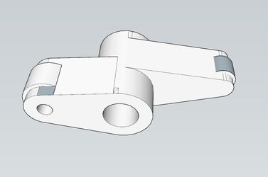
Calculated the valve spring pressure that I estimate is needed at 450 lbs open 200 lbs Closed and at 12000rpm and absolutely loads of lift, I recon those would last only a few minutes before a big problem would occur. Can't risk that so have drawn up some new roller rockers with rollers both ends and will adjust the valve lash with sized valve caps. I did do a complicated steel rocker but actually think this simple design will be much stronger and as this is a rocker and hopefully will be in balance so weight is not much of an issue, It will be in 7075 T6 Ally so not heavy anyway. and using Jessel Rollers designed for Drag racing big 500 inch V8s.
Despite the title, this pic is the Exhaust rocker and 1.3:1 ratio
The inlets are 1.5:1
Regards,
Julian
Calculated the valve spring pressure that I estimate is needed at 450 lbs open 200 lbs Closed and at 12000rpm and absolutely loads of lift, I recon those would last only a few minutes before a big problem would occur. Can't risk that so have drawn up some new roller rockers with rollers both ends and will adjust the valve lash with sized valve caps. I did do a complicated steel rocker but actually think this simple design will be much stronger and as this is a rocker and hopefully will be in balance so weight is not much of an issue, It will be in 7075 T6 Ally so not heavy anyway. and using Jessel Rollers designed for Drag racing big 500 inch V8s.
Despite the title, this pic is the Exhaust rocker and 1.3:1 ratio
The inlets are 1.5:1
Regards,
Julian
Attachments
Last edited:

Jo
Hero member
- Location
- Cologne, NRW Germany
I'm curious about the design of these valve caps. Isn't there a risk that those caps could dance or kind of flutter back and forth between the valve and the rocker arm? Or are my concerns completely unfounded?... and will adjust the valve lash with sized valve caps ...
Cheers
Jo
Hi JoI'm curious about the design of these valve caps. Isn't there a risk that those caps could dance or kind of flutter back and forth between the valve and the rocker arm? Or are my concerns completely unfounded?
Cheers
Jo
Most modern race engines use them nowadays when using finger followers
They increase the valve tip dia and are very hard, they are light press onto the valve tip and are about 4mm deep so they really stay put. Almost all titanium valves use them as ti is not very hard.
I have used them on many engines for years and never had problems. (Yet).
 )
Julian

GregT
Hero member
- Location
- Christchurch NZ
That'll work. I'd still like to see a full length top web as a stiffener.
Looking at a drag V8, those rockers are like a row of beam engines. Very industrial.
Giggle for you Julian - a mate here spent most of a day making an extension to his vaporblast cabinet and blasting a piece.
It's a magnesium sump from an Isotta Fraschini - about 1.3 meters long. Quote "It'll cost them!"
Looking at a drag V8, those rockers are like a row of beam engines. Very industrial.
Giggle for you Julian - a mate here spent most of a day making an extension to his vaporblast cabinet and blasting a piece.
It's a magnesium sump from an Isotta Fraschini - about 1.3 meters long. Quote "It'll cost them!"
Jo
Hero member
- Location
- Cologne, NRW Germany
Thanks Julian - I've no experience with titanium valves (yet) - this makes perfectly sense ...

Hi Greg,That'll work. I'd still like to see a full length top web as a stiffener.
Looking at a drag V8, those rockers are like a row of beam engines. Very industrial.
Giggle for you Julian - a mate here spent most of a day making an extension to his vaporblast cabinet and blasting a piece.
It's a magnesium sump from an Isotta Fraschini - about 1.3 meters long. Quote "It'll cost them!"
There is no room for anything on top of these in my engine, the valves are a good 1/2inch longer than std to get a good geometry and this brings the rocker nose up high, the beam though on these is actually thicker than a Big Block Chevy roller rocker I have here that was used in a drag engine with almost 1" of lift and 700lb springs so in theory I should be in the safe zone. I drew up some lovely fancy steel ones with super double webs etc but the weight was actually heavier than my expected blank, un-machined ally starting billet. Ally it is then

Isotta, yes these can be really big engines indeed. Fun project though.
Regards,
Jules
Light weight little babies!!!
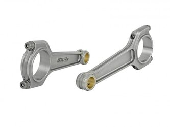
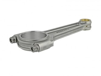
Just got me a set of these winging their way to me.
A std Carrillo rod weighs 594g
These weigh 384g each. Now that is a weight saving worth having!!! and they are 8mm longer than the Carrillo rods!
I can now at last start the final crank drawings.
.................... After I finish designing the new oil pump.
Regards,
Julian
Just got me a set of these winging their way to me.
A std Carrillo rod weighs 594g
These weigh 384g each. Now that is a weight saving worth having!!! and they are 8mm longer than the Carrillo rods!
I can now at last start the final crank drawings.
.................... After I finish designing the new oil pump.
Regards,
Julian
Attachments
piranha-bro2
Hero member
- Location
- Melbourne
Fancy stuff there, Julian! Huge weight saving. No doubt you need the oil pump redesign to feed the plain bearings.
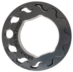
Is this ok?
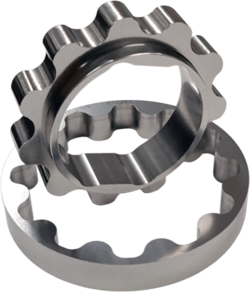
Nissan Skyline racing pump gears, specially treated to run at 13000 rpm,
Will be driven direct from the end of my crank and will be end fed to both ends of the crank.
No need to use the tiny original oil channels in the crankcase at all.
Running centre feed and 80 to 100psi it is calculated to work perfectly at 12k rpm.
Nissan Skyline racing pump gears, specially treated to run at 13000 rpm,
Will be driven direct from the end of my crank and will be end fed to both ends of the crank.
No need to use the tiny original oil channels in the crankcase at all.
Running centre feed and 80 to 100psi it is calculated to work perfectly at 12k rpm.
Attachments

Exmoor beast
Hero member
- Location
- Minehead,Somerset, ENGLAND OF COURSE
Dead interesting- I am interested in what speed the oil pump will reach cavitation- apparently on gear type Guzzi race pumps they can cavitate at prolonged high revs, maybe a different ball game with trochoidal pump.Is this ok?
Nissan Skyline racing pump gears, specially treated to run at 13000 rpm,
Will be driven direct from the end of my crank and will be end fed to both ends of the crank.
No need to use the tiny original oil channels in the crankcase at all.
Running centre feed and 80 to 100psi it is calculated to work perfectly at 12k rpm.
I know most Japanese bikes run oil pump at about half engine speed but your running 1:1.Love the Longer , lighter rods! Jason
piranha-bro2
Hero member
- Location
- Melbourne
Work of art, that pump. Are you running lines up to the cams/rocker spindles?
Hi,
The pump its self has been tested to 13k with no issues but my lines to it and contours inside the pump will be the deciding factor in cavitation, hopefully some careful thought and planning will sort that.
I will have lines feeding the cams via their ends after the oil cooler. The cams should actually need minimal oil as they are all on balls and the rockers all on rollers both ends and in the middle so only need a tad of oil to keep them happy, May need a little more for cooling the valves etc though.
Doing the body design etc in the coming weeks if I can get some time, a bit busy now but hopefully I can move the project on a bit faster in this end of the year period.
Will keep you all posted.
The pump its self has been tested to 13k with no issues but my lines to it and contours inside the pump will be the deciding factor in cavitation, hopefully some careful thought and planning will sort that.
I will have lines feeding the cams via their ends after the oil cooler. The cams should actually need minimal oil as they are all on balls and the rockers all on rollers both ends and in the middle so only need a tad of oil to keep them happy, May need a little more for cooling the valves etc though.
Doing the body design etc in the coming weeks if I can get some time, a bit busy now but hopefully I can move the project on a bit faster in this end of the year period.
Will keep you all posted.

chrisk
Hero member
- Location
- Brisbane, Australia
I’m thinking this monster is going to have ridiculous cambered front wheels and drift around every corner!