wanted - moto giro bike

The bike will look good, whether it wins or not.

The new rims are very shiny chrome, the spokes being made are polished stainless steel, the chrome now looks very good, and I have very high hopes for all the paint work presently being done.

I am presently polishing the wheel hubs and various other bits, including the engine clutch cover. If I can’t outrun the competition I will at least be stylin……..:cool::cool::cool:

The specialty welder just called, he is starting on my engine case and the cast aluminum muffler repair later to day apparently.
 
Got a shot of those sexy little handle bars Paul?

I’m curious why the platers don’t chrome the threads on things like the chain adjusters and the u bolts.
I should think that it's because of the thickness of the chrome which will hamper screwing the nut on.

Paul
 
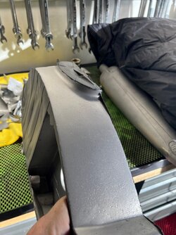
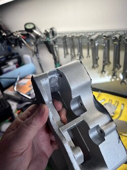
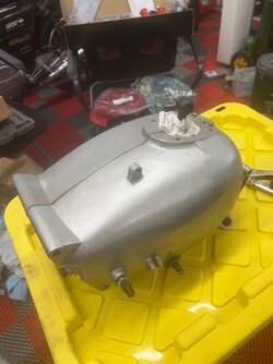
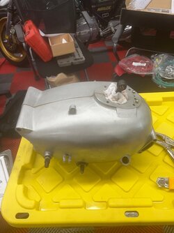
broken engine case half back from the welder. Photos titled engine case 4 and engine case 5, the middle part above where my fingers are in the photos was simply missing, a drive chain had broken and wiped out the back portion of the engine case, top and rear. No idea how he fixed it, the only thing I did when I got it back was hit it with a grinder then put it in my bead blast cabinet and kind of even out the texture with the rest of the case, and with the other case half. Derek the welder does amazing work.

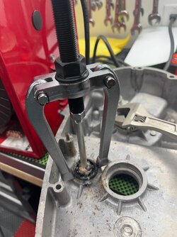
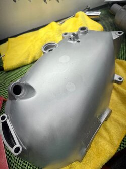
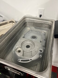
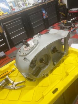
both engine cases are now ready for me to start fitting all the new bearings, I ran both halves through the ultra sonic a final time with clear water and just a tiny bit of cleaner to be sure I got the last of the blasting grit out of everywhere, then blew everything out with compressed air. Cases still show 65 years of use, but look 10,000 times better than when I started on them a couple of weeks ago. I am still polishing other bits, the clutch cover, wheel hubs, etc., going to try and resist mirror polishing the engine cases as well as it wouldn't take much now.........:rolleyes::rolleyes::ROFLMAO::ROFLMAO:;);)
 

Attachments

  • engine case 1.jpg
    engine case 1.jpg
    131.5 KB · Views: 48
  • engine case 2.jpg
    engine case 2.jpg
    112.1 KB · Views: 45
  • engine case 3.jpg
    engine case 3.jpg
    119.7 KB · Views: 44
  • engine case 4.jpg
    engine case 4.jpg
    130.8 KB · Views: 47
  • engine case 5.jpg
    engine case 5.jpg
    117 KB · Views: 49
Last edited:
broken engine case half back from the welder. Photos titled engine case 4 and engine case 5, the middle part above where my fingers are in the photos was simply missing, a drive chain had broken and wiped out the back portion of the engine case, top and rear. No idea how he fixed it, the only thing I did when I got it back was hit it with a grinder then put it in my bead blast cabinet and kind of even out the texture with the rest of the case, and with the other case half. Derek the welder does amazing work.

both engine cases are now ready for me to start fitting all the new bearings, I ran both halves through the ultra sonic a final time with clear water and just a tiny bit of cleaner to be sure I got the last of the blasting grit out of everywhere, then blew everything out with compressed air. Cases still show 65 years of use, but look 10,000 times better than when I started on them a couple of weeks ago. I am still polishing other bits, the clutch cover, wheel hubs, etc., going to try and resist mirror polishing the engine cases as well as it wouldn't take much now.........:rolleyes::rolleyes::ROFLMAO::ROFLMAO:;);)
the cases look so much nicer in satin finish, chrome is a bit too flashy, just what I think
 
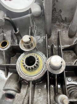
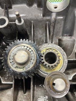
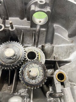
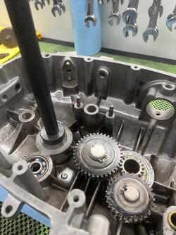
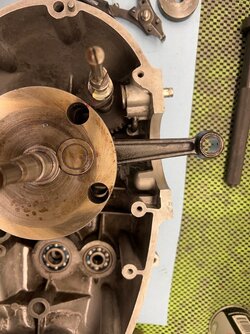
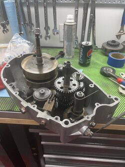
starting engine bottom end assembly, all new bearings
 

Attachments

  • assemble 1.jpg
    assemble 1.jpg
    171.4 KB · Views: 25
  • assemble 2.jpg
    assemble 2.jpg
    179 KB · Views: 23
  • assemble 3.jpg
    assemble 3.jpg
    153.5 KB · Views: 23
  • assemble 4.jpg
    assemble 4.jpg
    165.3 KB · Views: 25
  • assemble 5.jpg
    assemble 5.jpg
    176 KB · Views: 25
That is one of the best parts of a rebuild for me, reassembling the innards and closing it up. You have done everything you could to make sure you don't see in there again any time soon. Good work Paul.
 
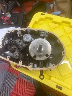
Thanks, Tippie! on that side of the engine, still the oil pump to install, make sure the transmission is shifting properly ( I had to totally dis assemble the shift drum and deal with a broken spring and a broken spring guide, need to be sure it is working properly) and fettle the kickstart mechanism. On the other engine case half have installed the new bearings and seals, should have the bottom end buttoned up by the end of the weekend if all goes smoothly.
 
further progress. Shifts nicely, kickstart mechanism seems to work fine. Only a couple in fasteners in place so far, need to trim case gasket in places. Felt a need to sort of seal the cases after their final very fine bead blasting in my blast cabinet, so sprayed and wiped them down with https://gibbsbrandlubricant.com/ I buy the stuff by the case.
 

Attachments

  • bottom end 1.jpg
    bottom end 1.jpg
    106.1 KB · Views: 28
  • bottom end 2.jpg
    bottom end 2.jpg
    96.7 KB · Views: 26
  • bottom end 3.jpg
    bottom end 3.jpg
    103.5 KB · Views: 27
  • bottom end 4.jpg
    bottom end 4.jpg
    131.7 KB · Views: 28
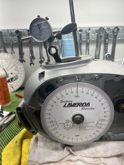
going to put a degree wheel on the crank end and figure out actual cam timing before I finish bolting it together. If I have to change cam timing by a gear tooth or two I would have to split the cases again

First however I have reached that stage of my project where it is time to clean up after myself and prepare for next steps. I started with a clean organized work area. Don't know why I make such a disorganized mess as I go, but time to put a bunch of tools away, put away the sanding/cleaning equipment, collect and throw out the garbage, and prepare for next steps.....

This feels like almost as much work as doing a full Jota rebuild, likely almost the same costs, good thing this 1957 Gilera 150 will be worth a fortune when I complete it.......:ROFLMAO::ROFLMAO::ROFLMAO::ROFLMAO::ROFLMAO::ROFLMAO::ROFLMAO::rolleyes:
 
trying to confirm proper cam timing, driving myself crazy with degree wheel and dial indicator, now drawing diagrams of the four strokes, bloody hell. For something so simple I seem to be working myself into a lather of frustration and self doubt. While I installed the cam exactly as it came out in relation to the crank, I have no confidence that the original loose assembly of the engine by hands unknown before me was correct, especially with absolutely no cam timing marks, and other errors that I encountered. Like my professional life, never trust anyone or anything without verifying for yourself directly independently.

From TDC, intake valve to open in first 180 degrees, second 180 degrees both valves closed, third 180 degrees both valves closed, final stroke exhaust valve opens last 180 degrees, from 540 - 720 degrees. Then overlap between intake opening while exhaust still closing, and I want to know what overlap is, in additon to what actual cam timing is, as is, then decide whether to crack the cases again, then figure out how many degrees per cam tooth gear, and which direction to change, if any. I am sure those that know what they are doing are laughing out loud reading this......:cautious:;)

Tried to use this exercise as an excuse to order another Mituoyo measuring device, this time a dial indicator, but Amazon is out of stock. Further, my enormous degree wheel is intended for a car, which further confuses me, going now to try and find the Laverda degree wheel files that fit DVD and print off, if I can find one..... Had to slip in some Laverda content;)

EDIT - found the printable degree wheel here https://www.laverdaforum.com/xf/threads/86485/ I printed it out on heavy high gloss photo stock, nice and sharp, and stiff. I have the first dial indicator directly on the intake tappet. Going to go pickup a second inexpensive dial indicator, mount it on the exhaust tappet, and chart intake and exhaust open and close, overlap, lobe centers. That will determine if cam is installed correctly in relation to the crank.

The intake tappet starts to stir at roughly 70 degrees before Top Dead Center as the exhaust stroke is completing, I understand there needs to be some overlap to help scavenge the last of the exhaust out. 70 degrees seems early to me but I know absolutely nothing.....:unsure::unsure::unsure::unsure: As the exhaust stroke completes the exhaust tappet is fully closed by almost exactly 0 degrees TDC while the intake tappet continues to lift. Maybe this is correct, but I am going to do all the measurements anyway with two dial indicators in place. Found a second dial indicator same as my original cheap one, on sale for $12.99, and another magnetic base on sale for $17.99, so will pick up both in the morning. Should be fine for my limited purposes
 

Attachments

  • Degree wheel on Gilera.jpg
    Degree wheel on Gilera.jpg
    144.6 KB · Views: 13
Last edited:
It sounds all right to me, I didn’t think it was too critical, excepting valve clash, past the working out you’ve already done? After all, you’re not regrinding the cam or anything.
But I’m interested to hear the experts!
 
Back
Top