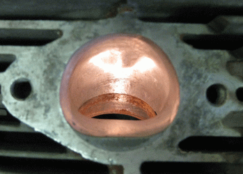
Flow bench numbers and engine simulation software

I'm interested in seeing CFM/lift and the vacuum depression the test was done at.  Does anyone have some test results they can share for any of the Laverdas?  After seeing the photo of the cutaway triple head in another thread it made me curious just how badly the stock triple exhaust port flows.

I'm not sure if I've got the numbers from my SF2RR or if that sheet went to Scott with the bike (or if I just never got the test results).  I'll keep a watch for them and post them if I can find them.

I bought an Audie Technologies Flow Quik recently and I'm going to see what mischief I can get up to on a Motobi head.  :)

I also got a copy of Dynomation 5 from motionsoftware.com and that has been pretty interesting to tinker with.  It sure generates lots of numbers and graphs, now I have to figure out what to do with all that information.

cheers,
Michael
 
Hi Michael,

Flow Bench only shows results for low-end revs. Sure if it runs there, high-end rev range will not suffer, but you simply can not simulate massive gas-exchanges done at 8.000 revs. simply impossible...

The head of my Jota got flow-benched and if I find the time (and the diagrams...) tomorrow, I'll scan them and post them here. However, that is a Tripple head and I am not sure if you are not talking about twins...?!?

Only thing I can say is that the measured head was a SFC head and there was just a very, very slight improvement possible with this head.

Other heads (like 3CL or RGS best) benefit more, as during the process the inlet channel can be modified much better - there is simply more "meat" you can make use of to design the inlet properly.

HTH
 
I'm interested in any of the bikes because I like to see what kind of numbers people come up with.  100/150/500/750/1000, whatever.

I'm not sure I'm reading your comment correctly but it sounds like you may be selling short the value of flow bench testing.  Sure, it should be validated with dyno time as the flow results don't always prove out in a running engine.  And just as with dyno numbers you have to keep a watch for people who quote "advertising" types of numbers.  But there seem to be a lot of pretty smart people with build really fast engines who spend an lot of time testing things on flow benches (often with a lot of money invested in those benches and the instrumentation on them) for them to be of only little use.

If flow bench numbers aren't representative of much it is surprising that the better simulation programs seem to be able to use flow bench numbers (among many other numbers) to make some fairly accurate predictions of the power that ends up being shown on the dyno.

I do know a pro engine builder that doesn't use his flow bench a great deal as he says he's already got a pretty good idea after 35+ years of what he'll do on most ports and when he does use the flow bench it is too easy for him to get sucked into doing more "what if I change this?" testing than he can afford to do on most jobs.

cheers,
Michael
 
Hi Michael,

I am not saying it does no good. Sure it is good to have meassurable results and sure it is good to see where the gas goes and what change has what effect. Flow-Benches primary benefit though is to visualize results of how good the man was that did the porting-job. And a standard Laverda-head surely benefits of it, as the intake and combustion chamber design is the biggest issue of that motor.

I would compare it with dyno runs like you did: It is good to see the results, but the changes that lead to the results are not caused by the dyno, they are simply just proven by it. And it also has the same issue like the (accelaration-type) dynos: Very often, the good results shown on it are not really there in the real world. F.e.: my bike was set up on the dyno. It showed a great, constantly rising power-curve. When I took it on the road, I almost could not accelarate in last gear. I had to drop the needle 2 notches (remember: Keihins have 7, so one notch is not really much...) to avoid it's pi**ing out the spark. And it's still way to rich...

The gas-flow is most important on low-end and midrange revs. In high-end revs (like 8.500 or so), you have more than 70 gas-exchanges per secound, which equal in rougly 23 Liters per secound that need to be sucked into the combustion chamber (all assuming a 1000ccm tripple at max revs). If you have an airbox, the airbox need to deliver almost 70 Liter of air per secound at that revs. That results in an airflow roughly at sonic speed. No gas in the world is fast enough to benefit dramatically (remark: I am not saying there is NO benefit...) from the better gasflow in your ported head at that rev-range I would say, even if your flow-bench shows an improvement of 3-4%. But that is just my guess, maybe I am wrong.

What also mostly is ignored is the turbulences the carbs and bellmouthes produce. Try to measure the head with carbs installed with either airbox or open bellmouthes) before optimizing and after and try the same without...  ;) Try Dell'Orto roundslide carbs and try Mikuni RS or other modern flat-slides. The difference you will see just with the different carbs will be impressively high I guess, maybe higher than any port-optimization. But the good news is: all benefits will sum up in the end, so porting the head plays into it, for sure. But only if the exhaust and everything else does not concur these benefits...  :D

BTW: Intake-length and Bellmouth-shape are two more factors not to oversee... Interesting article about it: http://www.profblairandassociates.com/pdfs/RET_Bellmouth_Sept.pdf

All that has an influence on how the gas really flows into the combustion chamber and are really hard to simulate on a flow-bench, especially not at revranges you need the power in. Typically, the shape of the piston top can also not be simulated on a flow-bench. So - if you have a "crown-type" piston, the gas distribution in the chamber can be different than with a flat piston etc. etc. And all that plays together but can not be simulated. But it is good to know that the intake can not be the problem anymore  ;)

The SFC 1000 head I once flow-benched got an improvement of 1-2 % out of it on the papers. I am not sure what the benefit really was, as I changed to many things at the same time. Overall, the Bike (1116ccm, high comp, 4/C, 180?) puts out a great power-curve and is a real joy to ride and has a good punch in low-end, allthough I use the 40mm Keihins on it which everyone told me will drop low-end and midrange torque. Maybe the ported head compensated that?!? I don't know...

Oh - and looking at your picture: a full fairing gives you more top-speed than any porting or other improvement on that bike ever will. I had one on the Jota when I bought it. Was amazingly efficiant. Even with 70HP the bike had back then, it was running 225km/h easily. With the half-fairing I have now it still goes up to that speed, but with almost 50% more power...  :D
 
Hi All - haven't had any heads put on a flow bench, but a couple of observations that may be useful:-
            On the triple head, on the inlet side the port shape tends to make the lower side of the valve not very productive - especially on the 1000cc models with the valve so close to cylinder wall. The last head i did was on Eglibob's endurance replica and, as that seems to be rated as a pretty quick machine, it may be down to the last  one off idea i did on the inlet ports. - I bored ports out to 36mm with end mill 1mm off centre to the down side - up to just before the guide boss. This left a 3mm step in lower part of the port that was hand blended smoothly into a nice hump  - the idea being to get the charge to lift up and away from the lower part of valve and give a possible bonus of a better venturi effect  in this area to speed gases up - always liked this idea in Phil Irving's books. The top of port was blended in as well - a 42mm valve was used with the top of the liner relieved around inlet valve area.  The inlet stubs and spacers were matched to the new port dimensions and the carbs bored out to 36mm - with thin wall extensions (bellmouths) fitted in a rebate machined in back of carbs - this enabled inlet tract length to be changed quickly and cheaply.  The exhaust valve was a "penny on a stick" 34mm item - i like these as they give a good flow when only just cracked open. The combustion chamber was made totally smooth by removing the "pockets" around the valves - we used to have our heads done by an ex Weslake tuner whose heads had  been used to win world championships  - i liked this process and have used it in nearly all of my own head modifications. Of course compression ratio and equal volume are critical too.
                  Hope this is of interest - will give an outline of work that i did on the SOHC twin heads if anyone is interested. - regards - Phil
 
A timely thread ...I`m just about to go through this process on a 500/600 cylinder head. Phil has already given me some valuable pointers and I`ll be dropping the head off with a chap in Yorkshire who comes highly recommended . I know bugger-all about gas flow or porting and I`m really looking forward to learning something.
Here's some questions I would like to know the answer to;

a] Is there such a thing as an optimum porting job, or can you port heads in such a way to impart  certain characteristics in a motor, such as profiling ports to generate high velocity to help with torque or alternatively profile it to flow big volumes of air.

b] Can a standard type valve be reprofiled into the 'penny on a stick' shape, I`ve always wondered why Phil favours these and his succinct explanation in his post now explains the benefits of the shape.

c] What actual info do you get from a flow bench and how is it presented? Do you get a cfm/minute figure. Presumably you need to know what the head flowed before you do any modifications.

And finally, I was wondering about leaving the inlet port walls with a textured/ dimpled finish to help with laminar flow. My very limited experience with aerodynamics suggests that this might be beneficial. Any thoughts or data on this?
 
Hi Michael, Phil, Noneglibob (cool name by the way - made me smile  :D),

a) bob: generally speaking, the targets are 1) to bringe each gas molecule as close as possible to one air molecule so that they can react with each other 2) to improve the amount of gas and air atomes by improving gas flow in the channel and reduce restrictions. You run a compromise here, as both concure with eachother (wider channel - less air-speed, narrow channel, higher restricitions). To compensate the weak airflow of a wide channel in low revs, you need to shape the channel so that the gas and air mixes best possible. That is less of a problem in high revs, as due to the very high speed of the air, the atomization of the gas quiet good, even in not 100% accurate shaped engines.

b) don't know. Phil?

c) see attachement

to the point of the surface of the inlet: NEVER POLISH IT!!! the rougher (homogenious...) the surface, the better. Exhaust however would benefit potentially from polishing. The same on the Valves: On the inlet-side, you should not polish it (or polish it and give it a rough finnish) to improve gasflow. The under-site of the valve however should ALLWAYS be polished, the same on the top of the exhaust valve. Polished valves have less surface and therefore take less heat.

HTH
 
Hi all - Don't know the answer to (a) - with computer aided development now so advanced - I guess some manufactures/race teams are probably already doing this.
          (b) I think you could grind a valve to this shape, but don't like the idea of any work being done to a valve in that critical area - best to use one made in it's original form. As yours is a 4 valve head you are not struggling for valve area so i wouldn't deem it that critical to have the "penny on a stick" ex valves.
  (c) - If Lothar's attachment was attached we would all know  :D :D :D
 
        I usually end up with polished ports as that's what happens when you blend everything in nicely - I think a polished, then beadblasted port is very good for flow and keeping the mixture fully atomised. - Regards - Phil
 
Laverdalothar said:
Hi Michael, Phil, Noneglibob (cool name by the way - made me smile  :D),

a) bob: generally speaking, the targets are 1) to bringe each gas molecule as close as possible to one air molecule so that they can react with each other 2) to improve the amount of gas and air atomes by improving gas flow in the channel and reduce restrictions. You run a compromise here, as both concure with eachother (wider channel - less air-speed, narrow channel, higher restricitions). To compensate the weak airflow of a wide channel in low revs, you need to shape the channel so that the gas and air mixes best possible. That is less of a problem in high revs, as due to the very high speed of the air, the atomization of the gas quiet good, even in not 100% accurate shaped engines.

Generally - when speaking of 2-stroke-port-design - a D-shape is considered to be the best compromise between swirl and throughput

Laverdalothar said:
b) don't know. Phil?

Yes there is, basically every obstacle like valve guides etc. that is protruding into the port is causing swirl and is lowering the throughput.

Laverdalothar said:
c) see attachement

to the point of the surface of the inlet: NEVER POLISH IT!!! the rougher (homogenious...) the surface, the better. Exhaust however would benefit potentially from polishing. The same on the Valves: On the inlet-side, you should not polish it (or polish it and give it a rough finnish) to improve gasflow. The under-site of the valve however should ALLWAYS be polished, the same on the top of the exhaust valve. Polished valves have less surface and therefore take less heat.

In terms of the exhaust port, I agree with Lothar, but NEVER mirror polish the combustion chamber or the ports, this may lead to magnifying-glass-like effects. In terms of the inlet, a certain roughness is required to aid the swirl. But this roughness lies in the area of what may be achieved with a 1000 - 2000 grit sanding paper.

Valves may be polished. (and as it shows is a point of ongoing dispute - personally I believe in a polished valve for the simple sake, that the gas flows around it faster. If you're after a certain kind of valve-shape check the automotive industry and see what can be modified to fit). Personally from building fast Suzukis and Kwaks, the Kibblewhite-S/S-Valves are really nice and you can have a special made for you on order.

Cheers,
Greg
 
phil37 said:
  (c) - If Lothar's attachment was attached we would all know  :D :D :D

Sorry, the filesize is 1,7 Mb and the page does only allow for 300KB...

Anyone interested pls. send me your mail-Adress via PN, I will send it out by mail then.
 
Hi Greg,

the intention of polishing the surface has more to do with a) reducing the surface so less heat can merge into the part and b) less "dirt" can stick to a polished area than to a rough one. Velocity defenitely is better if the surface is rough. As far as I know at least... Beadblasting is I think the best way but needs very good cleaning...
 
Laverdalothar said:
Hi Greg,

the intention of polishing the surface has more to do with a) reducing the surface so less heat can merge into the part and b) less "dirt" can stick to a polished area than to a rough one. Velocity defenitely is better if the surface is rough. As far as I know at least... Beadblasting is I think the best way but needs very good cleaning...

Ok, I guess this is where things get a little blurry, I would assume, that less resistance leads to higher velocity -> polished
The flow it self is the product of velocity and free-port area (for simplicity the diameter).

The thing missing in this equation is the swirl, which is vastly improved by a rough surface and is also needed for a proper mixture, no point in flowing gas fast, but literally having "drops" fall out of the stream.

Just my 0.02 Euros on this...
Greg
 
Hi Greg,

I can not proof what I said as I am not a technichian and the following example surely is very blue-eyed, but I think to remember that golf-balls are shaped as they are for two reasons: a) because of better stability of their flying curve and (the reason for a) ) b) because of less resistance facing in the air.

The stabiliy with a smoother surface is worse because the ball "hits" against the air. The rough surface devides the airstream in several small ones which get around the ball easier and also help to stabilize the flight-curve with it. That would play together with your assumption that a rough surface produces swirls but your conclusion is a different one. You think swirls are reducing the airflow, I think they can even improve it.

I may be totally wrong here, but that is at least how I was told from a tuner I read some infos from and it made sense to me. Michael will be able to measure that with his new flow-bench, so he can either proof you or me wrong. :D
 
i'm not sure i'm reading the images correct but my initial thinking is they all illustrate the best flow in a D shaped area. best way to do this is to raise the port floor. lost cross section can be picked up by widening the port. here's a pic of a street ported 750 head. the manifold also has a gentle ramp to match the port floor.

port walls are best left rough, beadblasted finish is fine. i use 240 grit flapper wheels. the boundary layer adheres to the coarse walls allowing greater laminar flow next to the boundary layer. a polished or smooth wall reduces port volume as the boundary layer is much thicker. the effect is significant. save polishing for the chamber and backs of valves to reduce deposits.

i'm not sure how to measure or obtain swirl in the port proper, esp with pulsations from valves opening and closing, and suspect it is more important for the mixture to swirl into the cylinder and chamber. some manufactures do this by slightly offsetting the valve in relation to the port. with a 4 valve head you can have one inlet open a moment before the other. its an effective cheat to create swirl.

to get to bob's questions;

finding an optimum port shape will be a compromise between extremes. while a port can be optimized for a given rpm and to a lesser degree the different harmonics of the wave flow caused by valves opening, closing and length of inlet tract every where else it falls short. to begin to find an optimum port for a given application begs questions about what kind of power at what kind of or range of rpm

different valve shapes have different flow characteristics and are affected by direction of airflow and cant of valve in head

flow benches are calibrated using a fixed orifice and a recording of measured vacuum at the orifice, temperature and humidity. not so different from a dyno. you have to have a repeatable or correctable baseline. two identical benches will produce different numbers on different days or with different operators using the same head. so they can be calibrated to cfm or the metric equivalent no big deal. flowing the head before modification gives one a baseline. they are also handy for comparative airflow so all the like ports flow the same

textured, absolutely. dimples are used to help move the flow or improve dead spots. how i'm not certain. most of the guys that think they know don't like to talk about it.

engine simulation software has come a long way. the best ones use wave action analysis accepting flowbench data or airflow and able to compute what it does at what kind of rpm you want all while including variables like rod angle and crankshaft bob weights. very cool. i'm using version 3.01 without near the input variables. here's the link to one of the pioneers in simulation http://www.audietech.com/

cheers,
scott


Attachments

  • inlet-port.gif
    inlet-port.gif
    145.1 KB · Views: 45
Hi Lothar,

The early version of my 750 was run in an AMA Battle of the Twins class that didn't allow adding a fairing, but seats were free.  Often times the back of the bike is more important aerodynamically than the front.  A 2" narrower version of that seat, when put on a nearly stock CB125 Honda single (which might have had all of 7 or 8 hp) added an extra 500-800 RPM in top gear with no other changes to the bike.

When I built the MK4 chassis for the racer for the F750 class I added a H-D XR750 long track fairing to it:

http://www.eurospares.com/graphics/Laverda/SF2RRLeftFront1.jpg

Scott says it is looking good to have the racer on the track next year so I'm eagerly awaiting a report on how it goes.  I never raced it with the fairing, the newly designed Megacycle cam, JE pistons or the titanium valves.


The Blair papers are all quite good.  I look forward to them when they appear in Race Engine Technology magazine though at times they get a bit too heavy in the maths for me.  David Vizard also seems to have a good understanding of what is going on in an engine and you can read a series of articles by him on porting that start with this page:

http://www.gofastnews.com/board/technical-articles/980-porting-school-2-super-cheap-flow-bench.html

The people who really seem to know what they are doing often do a test of the complete intake or exhaust system on the head as there's no sense having the best port in the world and then putting on a junk manifold that eliminates 120% of the improvements that you made in the cylinder head.

Here's a scan of a page from David Vizard's "Theory and practice of cylinderhead modification" that shows how a "fat" underhead radius on the intake valve restricts the available flow area in the port at lower lifts.

http://www.eurospares.com/graphics/engine/VizardValveProfile001.jpg

FWIW "swirl", at least in the USA and UK, has a specific meaning for engines.  Swirl is a rotary motion about the cylinder axis of the gases in the cylinder.  Tumble is a similar motion but around an axis 90 degrees to that.  Here's an illustration:

http://tinyurl.com/y95fx4a

Swirl tends to be a concern in two valve heads, while tumble is a characteristic of four valve heads.  Jack Williams picked up a bit of power on the AJS 7R by offsetting the intake port a little so as to add some swirl to the mixture in the chamber.  It helps promote better combustion.

Scott explained lots of things.  An ideal port will be straight and round.  Square, D-shaped and oval ports come into play when you try and fit that ideal port into the constraints of a real cylinder head.  :)

You can buy instruments to allow you to measure swirl on the flow bench from places like Audie Technologies.

Scott, you mention using version 3.01 but not which program.  Is it Dynomation?  You can download the current user manual at

http://www.motionsoftware.com/downloads/Dynomation-UsersManual.pdf

if you want to see what is going on in the newest version of the software.

cheers,
Michael
 
Laverdalothar said:
I may be totally wrong here, but that is at least how I was told from a tuner I read some infos from and it made sense to me. Michael will be able to measure that with his new flow-bench, so he can either proof you or me wrong. :D

I think to remember from some lectures, that the golfball was considered to be a paradoxon... ;-)
Nevertheless, I have the strong feeling, we shall have a beer at the next rally or so...  :D

Cheers,
Greg
 
Defenitely, I am allways for a beer!! And just to avoid missunderstanding: I am discussing to help with what I know and to learn what I don't know. I am 300% OK if what I said is totally bullshit. If someone can proof, I am more than happy to learn. OK?  ;)

For the golf-ball-effect, see Wikipedia (which is not always right, but a good first source...):

english: http://en.wikipedia.org/wiki/Golfball#Aerodynamics

Deutsch: http://de.wikipedia.org/wiki/Physik_des_Golfballs

It seams to be quiet clear it is no paradoxon but pure physik. One reason, even Schubert did a Bike-Helmet in that design (and remember? the surface was - matt de luxe, not shiny... :-)
 
Laverdalothar said:
It seams to be quiet clear it is no paradoxon but pure physik. One reason, even Schubert did a Bike-Helmet in that design (and remember? the surface was - matt de luxe, not shiny... :-)

Oh, I remember that helmet, I used to be a very small child at that time.  :D
(And I still have to fight the temptation of building a flat-black Laverda  ::)

With regards to the golfball-effect, I was obviously mistaken... but think god we came to a conclusion in terms of the beer  :D

Cheers,
Greg
 
It is hard to NOT to agree on beer with a guy from Cologne (like me)... The only question ist - do we have the same understanding of what is a beer? :o

Fortunately, I am not exactly from Cologne but 15Km east. We call the area the "neutral area", as we drink all kind of beer. Well - except "Alt" maybe...

:D
 
Back
Top