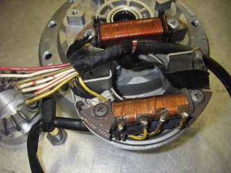
180 degree triple electrical woes

If it is all live no matter what position the ignition key is in then either the ignition switch or the wiring to/from it are fucked. If Wolfgang has checked the switch then the wiring is the problem.
 
First of all, you will need to verify that all individual components work as they should, ie, test coils, test pick-ups, test DMC unit.  Once these test out OK, you can start looking at why and where the fault lies.  COMPLETELY DISREGARD THE CHARGING CIRCUIT (yellow and yellow/black wires to R/R unit) FOR THE TIME BEING!  It is totally irrelevant for getting the engine running.  All you really need is a fully charged battery in GOOD condition and a little patience.  DO NOT ASSUME ANYTHING, CHECK!

The coils are first.  Power one up with +12V, attach a cable to the other connection and tap it to ground, you should have a spark at the HT lead.  Repeat for the other coil. No spark; coil/s fucked.  Repeat with caps and plugs attached.  If the spark disappears, plug and/or cap fucked.  Caps should have 5-10 kOhms, plugs no resistors.

The DMC I unit can be tested by powering it with +12V, switching dip-switch 4 to (I), connecting the (verified to be working) coils and shorting either the blue or yellow pick-up cable to the black cable (ground) to simulate the pick-up, a continuous spark should result at the HT lead (do hope I've got that correct... don't have a DMC I manual to hand at the moment :D).  No spark; DMC fucked.

For the pick-ups, the flywheel must be removed to gain access.  The pick-up wiring MUST be inspected CLOSELY for damage/insulation break-down (each individual wire along its entire length!).  If all checks out OK, you can measure the individual internal resistance of the pick-ups, should be around 50 +/-10 Ohms iIrc.  The pick-ups themselves very rarely give problems, they are extemely reliable!  The wires however, deteriorate after 30-odd years of use.  Connect the pick-ups to the (verified to be working) DMC and coils, power up with +12V and place a screwdriver blade over the magnetic poles of a pick-up.  You should have a spark at the HT lead when you REMOVE the screwdriver blade.  If you have a spark when the screwdriver blade TOUCHES the pick-ups, you have the polarity of this swapped.  Swap the leads to the DMC.  Repeat for the other pick-up.  No spark; pick-up/s fucked.

If these things all check out OK, you can at least be sure the ignition circuit is working.  If you still don't have a spark, the power supply to the ignition system is at fault.  If ignition system powers up OK when the switch is flicked, you may have the starter drawing too much current on cranking.  Check that at least 6V remains at the DMC and coils WHILE CRANKING.  If you have less, the DMC will not work.  Check and overhaul the starter motor and/or relay.

Jumping from one item to the other before verifying any one of these are in working order is simply a waste of time and energy.  Work methodically and apply logic/common-sense...

piet

 
Thanks for the detailed response Piet.  Apply logic/common sense...always good advice.

One question concerning the DMC unit - there are no switches on the box so when you say "switch dip-switch 4 to (I)" I don't understand what I should do.

This all sounds pretty tricky but if I take my time I hopefully won't fry anything.  Time to get serious and find a flywheel puller.
 
Piet's spot on as usual!  Just one thing - the DMC1 test facility doesn't provide a continuous spark like the DMC2.  It just gives a single spark when triggered.  See attached manual p11.  Make a note of the 'as found' switch positions before changing anything.

The DIP switches are hidden under a plastic blanking plug in the blue aluminium DMC box -plug should be covered in tape for guaranteed waterproofing.
 

Attachments

Hi Rob - thanks for sending me the manual, that is a big help.  I've been exchanging emails with Wolfgang and he told me about the plug to which you refer so I'll look for that tonight.  All you guys are an amazing resource.  Your help and patience are much appreciated.
 
The switch on another systems box I used to play with was that small you needed your glasses for sure to read it and a jewelers screwdriver to adjust it.
 
Hey as you say that you have an issue with the switch being on all the time then just for shits and giggles tell me what position the head light switch is in ? if its in the on position 9 or park light for that matter ) turn it to the off and see if any difference. As have seen and heard of for that matter feedback through this circuit cause a similar type of issue.

As for not starting then advice and go back to basic 101 trouble shooting... first thing you need to verify is do you have +12 at the + side of the coils with the ignition on ? Then either work back or forward from there as per Piet's detailed troubleshooting .
Listen to him my friend he has a wealth of information as this is what he does.

If it makes you feel any better am just heading off for a 6 hour one way drive to see if can get a truck running with a very similar issue to yours by the sounds of it.. arrrg its bloody 24 V which you think 12 V is a challenge oh and did I mention its Chinese so no wiring diagram's  :D at least i should be able to hot wire the Cummins side of it to get it to start .... well that is the bloody plan.
 
Too Late Cam, it's fixed thanks to Rob. 

I know I may be evicted from the Forum and cast into the wilderness when you hear this.  I'm used to being the dumb kid in the room but I've achieved new heights this time. 

Rob sent me a copy of the manual for the DMC unit in the bike in preparation for running the diagnostic tests outlined by Piet.  I read through it and on page 5 there it was -  "the black leads must be connected to the negative terminal of the battery".  I am always very careful to label the wires when I take a battery out of a bike but somehow I screwed this one up and connected the aforementioned black wire to the positive terminal.  The manual goes on to state that "the unit is more or less impervious to damage from wrong connections" which must be true because when I switched the wire over to the negative terminal I got a nice fat spark on all cylinders and all the weird wiring stuff I've been seeing like the starter running with the ignition off vanished.

I've learned a lot about this bike through this experience but at the cost of your considerable time, effort, and patience in trying to help me out.  I owe you all a profound apology.

I'll start looking for a box to put it in Cam.  If Cam decides the $150 price is too steep I will need help coming up with a price as I very unfortunately have to sell all my bikes, the 3C(E) included.  Once the bike is assembled and running and I take some more pictures I'll open a new thread in the "For Sale" area (assuming I haven't been barred from the forum for overt stupidity) and maybe you guys can give me your opinion.  The basic question will be whether the (E) part of the 3C(E) really makes a difference or not.

Thanks again for all your help.  I have to pull my 1975 SFII out of storage this weekend.  Who knows what gremlins await...
 
And just when I thought I was done...Wolfgang insists that, since I have the bike apart anyway, that I pull the magneto cover and really check the wiring to make sure nothing has decayed over the machine's 40+ life span.  Piet made a similar suggestion about carefully checking each pick-up wire for its entire length.  If nothing else it will be good to be able to assure any prospective buyer that the wiring is OK.  Plus Wolfgang is shipping me his personal puller since he doesn't have any others available - how can I say no to that?

My question is, is there anything I should be particularly wary or careful about while performing this exam?  Based on my performance thus far I don't want to make a hash out of the operation.  My sole guidance is my trusty copy of the Green Book so any wisdom you can impart will be welcome.
 
Hi John

Once you have the alternator rotor off, check that whoever installed the Witt system has also replaced the old ignition feeder coil with another charging coil. The alternator stator should consist of two identical copper wound coils, one at the top and one at the bottom of the stator plate. If your stator looks like the one below, you need to toss the double coil pack at the bottom and install another charging coil the same as the top one. You should also fit a regulator rectifier if one hasn't been fitted already.

Cheers,
Cam
 

Attachments

  • coil%203[1].jpg
    coil%203[1].jpg
    39.1 KB · Views: 36
Dellortoman said:
The bike is completely buggered. I'll give you $100 for it.


PS: I've sent you a pdf of a colour-coded wiring diagram for a 3C.

If during your pre-start checking, you cranked the motor over with the plug leads disconnected and not earthed, the ignition system may be fried. Those old original Bosch HKZ ignitions were pretty fragile in that way.

BTW, welcome to the forum

Cheers,
Cam

Damn Cam, it hs to be worth at least $200 in melted metal  :o :o :o

John are you still in Florida. Ant BTW, was it really Florida or not having the bike  8)

Welcome to the forum, you have access to the greatest amount of knowledge about Laverda's anywhere in the world.

Clay
 
Hey Cam - thanks for the response and photo.  Is the double coil pack on the bottom the feeder coil you say I should toss?  Also, I know the bike has a rectifier - is a regulator rectifier something different?...revealing my ignorance once again.  I'll take a photo of what I find inside and see if I can post it.

Hey Clay - yes, I'm still stuck in Florida.
 
TBH, if your plan is to sell, then I wouldn't bother doing any more work than necessary to demonstrate the bike us a runner.  You won't get your money (or time) back. 

The swap Cam mentions was a vain attempt to increase the weedy alternator output - but it still remains weedy.  As it is, the original arrangement reduces the need for a reg/rect in place of your rectifier (needed to convert AC from the alternator to DC for the battery) since the original coil provides some regulation itself.  The regulator part of the reg/rect just limits the DC voltage to avoid overcharging the battery - which becomes an issue with higher alternator outputs.
 
https://www.flickr.com/gp/143907356@N06/6c082m

Back again.  I pulled off the magneto cover to check things out, particularly the wiring.  I took several pictures which, of course, I couldn't figure out how to post here so they're on my Flickr account posted above.  If you highlight the address, right click and then click "go to" it seems to work.

Anyway, it looks like I have the two coils Cam thought I should have.  All the wiring looks good.  only question is, in the Green Book Parker makes a point of showing that the mark on the coil plate line up with the mark on the crankcase.  As found when I pulled the cover off, the mark on the coil plate was several millimeters to the left of the crankcase mark - you can see it in a couple of the pictures.  I added the black mark on the crankcase so I'd be sure to return the coil plate to its starting position.  Do I leave it as I found it or move the plate so the factory marks line up?

Thanks as always for your help.
 
Back
Top