3C wiring

Leaps and bounds I tell you, leaps and bounds.

I first thought that I'd need to start at the rear light and work my way forwards. No.
Then I thought that I'd need to find a central point for the loom and go back and forwards from there. Getting warmer. I used the neutral wire switch as a central point. Bad idea. I at first thought that the loom I'd bought was a piece of crap because there was no wire to control the starter relay and the wiring for the fuse box was behind the air filter. Well, that harness isn't crap, it's just darn expensive for a few and connectors and heat shrink. There was also about a foot too much loom at the headlight.
Then it dawned. Right technique, wrong centre. The loom needs to be centred around the fuse box. Then, the wire for the starter relay is just right along with the feed to the ignition and the big hole in the back of the tool tray from where I remember pulling the harness out a year ago and which was empty, is filled with harness to the rear light, the fuse box wiring, the rear brake switch wiring and the neutral switch wire.
It's all in place so that I can now move up to the headlight to wire in the handlebar switches and the instruments.

We have lift off.

Paul
 
Thanks Todd. That confirms that the later incarnation of the M-Unit has the "lights off" capability in the software. Grant did his in 2010 and it was definitely not an option back then. Blimey, has it been that long? 😲. I feel old.
 
Thanks Todd. That confirms that the later incarnation of the M-Unit has the "lights off" capability in the software. Grant did his in 2010 and it was definitely not an option back then. Blimey, has it been that long? 😲. I feel old.
Not old, just wiser-
 
Thanks Todd. That confirms that the later incarnation of the M-Unit has the "lights off" capability in the software. Grant did his in 2010 and it was definitely not an option back then. Blimey, has it been that long? 😲. I feel old.
dude you arent old and shouldnt feel it... if anything you should feel how valuable you are!
 
In response to Paul's questions about wiring up his 3C with the Redax (Ignitech) ignition and alternator upgrade, I did a modified 3C wiring diagram to include that upgrade. It's in the Library section here: https://www.laverdaforum.com/xf/resources/95/history

I also did a diagram showing which bits of the original electrical system to remove before wiring in the new stuff. But I dunno whether it's worth putting that in the library because it's all pretty obvious what gets discarded. HKZ ignition, pickup plate (including alternator coils), rectifier, stop relay and a bunch of associated wiring is all redundant must be removed. But if anyone wants that diagram, I can upload it as well.

After all that stuff is gone, you'll need to find somewhere to mount the ignition box, coils and rectifier/regulator. I think Red includes pretty detailed instructions so I won't waffle on about it here.

The only bit of all that old ignition/alternator sub-harness that you may choose to keep is the little connector strip that all the pickup and alternator wires go to. It usually sits on the frame just behind the tank. You can re-use that for the new installation, or make soldered joins in the wires, or get some multi-pin plug type connectors. How you graft the new stuff into the bike's existing wiring is up to you. For the purpose of keeping the diagram simple, I've just shown the original connector strip re-purposed.

PS: I'm as capable of making mistakes as anybody. So if anyone spots an error in the diagram, let me know and I'll amend it.

PPS: The reason I did this is that Paul asked me what to do with the kill switch when the stop relay is removed. I understand that the stop relay can be a bit confusing. It confused me when I first came across it. The answer is that the the wire that goes from the kill switch to the stop relay is a switchable 12V feed that energises the stop relay while the engine is running, so it can be re-purposed as the power feed to the new ignition system. The kill switch will then still work as an engine stop switch.
 
Last edited:
Thanks Cam.
I was meaning to answer you in private but here we are.
I had got a bit mixed up with that redundant blue wire coming from the right hand switch unit. It will be used to feed the ignition of course. I will start mounting the ignition this afternoon. Even though the right hand crank end is new and nicely polished, it's going to need a bit of easing with wet end dry to ensure the ignition trigger is free to slip on.

Thanks very much for the diagram.

I have another question.
The ignition switch that was on the bike when I bought it has been rewired, probably to be permanently on, since the functionnal switch was under the saddle for some reason. When my friend had it, I remember there being electrical problems.

I have a spare ignition switch which I'll be using. It has 4 wires, red, brown, orange and grey.
The grey will be made redundant, so I'm left with the red and the orange, side by side on the back of the switch and the brown opposite.
Red and orange on the diagram are terminals 30 and 58 but which is which? Forwards most one on the back of the switch is the orange wire going to a terminal marked 2 on the switch. I presume it to be 30 which goes to the regulator, the battery + and the fuses.

Paul
 
I never rely on wire colours to identify what's what. It's safer to use the numbers labels that should be printed on the back of the switch. They comply with the DIN standard for automotive wiring (DIN 72552). You can find a list of what the numbers mean here: https://en.wikipedia.org/wiki/DIN_72552

30 is the 12V supply direct from the battery (via a fuse of course)
15 is the switched 12V feed to the ignition and other circuits
58 is parking lights

If there are no numbers on the back of the switch, you'll have to work it out with a continuity tester (a multi-meter on a low resistance scale or a battery and light globe or buzzer). It's pretty simple. I always test the function of any switch before installing it.

I'd guess that the red wire is the primary battery feed (#30), so start with that one and connect it to one probe of your continuity tester.

I presume it's a 3 position switch. With the key in the "OFF" position, touch the other probe of your continuity tester to each of the other wires in turn. There should be no connection to #30 on any wire.

Go through the same procedure with the key in the "ON" position. You should find at least one wire that has continuity to #30. That will be #15, the ignition feed.

Switch to the "PARK" position and do it again. This time the live wire will be #58.

If you find that the switch doesn't behave as described above, then perhaps the red wire isn't #30. Select another wire as the primary feed and do it all again. You'll get there eventually.
 
I never rely on wire colours to identify what's what. It's safer to use the numbers labels that should be printed on the back of the switch. They comply with the DIN standard for automotive wiring (DIN 72552). You can find a list of what the numbers mean here: https://en.wikipedia.org/wiki/DIN_72552

30 is the 12V supply direct from the battery (via a fuse of course)
15 is the switched 12V feed to the ignition and other circuits
58 is parking lights

If there are no numbers on the back of the switch, you'll have to work it out with a continuity tester (a multi-meter on a low resistance scale or a battery and light globe or buzzer). It's pretty simple. I always test the function of any switch before installing it.

I'd guess that the red wire is the primary battery feed (#30), so start with that one and connect it to one probe of your continuity tester.

I presume it's a 3 position switch. With the key in the "OFF" position, touch the other probe of your continuity tester to each of the other wires in turn. There should be no connection to #30 on any wire.

Go through the same procedure with the key in the "ON" position. You should find at least one wire that has continuity to #30. That will be #15, the ignition feed.

Switch to the "PARK" position and do it again. This time the live wire will be #58.

If you find that the switch doesn't behave as described above, then perhaps the red wire isn't #30. Select another wire as the primary feed and do it all again. You'll get there eventually.
Thanks for that.
Seems obvious when you know.
Some things are intuitive, some aren't which is maybe why electrics scare people, including me, off.

Paul
 
Thanks very much Cam.
Done with a bulb. Not sure I know how to use my multimeter.
Red is indeed 30 and orange is the switched feed 15.
Brown is 58 parking position.

Paul
 
Well done Paul. There's no need for anyone to be scared of electrics. It's all very logical.

I never got my head around electronics though. I suspect micro-processors work by magic.
Thanks.
It's computer programming that put an end to my belief that I could simply understand and master my environment.

Paul
 
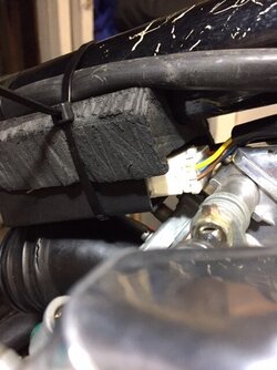
I wired my Ignitech that way. Works great including kill switch. Box fits (barely) under backbone behind carb bank. Fashioned an appropriate 'under saddle' out of high density black 'sponge' as found in Champagne packaging. Single zip tie holds it. Wires to (Nology) coils (mounted same area as originals) just the right length. I found the connector block hanging off the frame when I got bike. Some wires barely connected by a strand or two. How did this bike even run!
 
I wired my Ignitech that way. Works great including kill switch. Box fits (barely) under backbone behind carb bank. Fashioned an appropriate 'under saddle' out of high density black 'sponge' as found in Champagne packaging. Single zip tie holds it. Wires to (Nology) coils (mounted same area as originals) just the right length. I found the connector block hanging off the frame when I got bike. Some wires barely connected by a strand or two. How did this bike even run!
Have you got any photos before I finalise my installation?

Paul
 
Just the Redax kit to go. Loom is all wired up though I'll have to tidy up in front. No way is that headlight going to close.
A small satisfaction having wired up the ignition switch was putting the key in with the key fob the bike had when it was taken off the road 25 years ago.

Paul28 3 21.jpg
 
Got there.
Many thanks to all, particularly to Cam who guided me through a lot of this.

When I finished wiring, I wired up a battery, and.....nothing.
So I went back to the diagrams and guessed I was missing a feed to the circuit. That was the case.
When that was corrected, I had a nice green neutral light, working lights but nothing happening ignition wise, an Ignitech.
So it was step by step, checking all the Ignitech wiring and testing wires.
It turned out in the end, that when refitting the connector to the ignition plate after having passed the wires through the cases, I'd got it wrong. I don't know how since I was very methodical, but wrong it was. I was feeding juice to the ignition plate earth and expecting the box to feed the ignition plate with an earth.
All fixed now. It's timed and there's a spark. I'll double check tomorrow and then it'll be time to put the exhaust on the machine. After which, petrol and vrooom.

Or so I hope.

Paul
 
All fixed now. It's timed and there's a spark. I'll double check tomorrow and then it'll be time to put the exhaust on the machine. After which, petrol and vrooom.

Or so I hope.

Paul
Not your first Laverda rodeo-it's gonna be a screamer! Post a vid of the vroom as I enjoy living vicariously...
 
Back
Top