4th Gear Problems, Options

Greg and all, this information is invaluable. I've learned a lot in just one day.
I've found a company 1 mile away who has shown interest too and likes Laverda's so I'll call in and see him next week.

Scott/Keith, it'd be good to see the photo of the SFC gear and  scroll machined shaft if you have anything there.

Any ideas how an EN36 gear might react to rotating direct on the Mainshaft without bush?
 
Greg, hold that thought.
At the rate folk are fitting RS36 carbs and other performance helpers maybe there will be a need for stronger gear cogs.
 
Grant - the use of the word 'cog' is an assault on engineering terminology.  :'(  Please desist!  They're gears, NOT cogs!! 

Pedantically yours

Brad
 
Re running hardened steel gear against hardened steel shaft - unless you can guarantee a pressure supply of lube don't do it.
I'd suggest that a good grade of phosphor bronze for your internal bush would work well.
As an added bonus it's one less precision grinding job - the bore can be left finish machined - a good fine finish will do, then a bush made to suit.
The sleeve gear on the Macchi set is ground internally for needle rollers and externally too - not cheap....
 
The shaft looks like it is showing typical signs of fatigue with the consistently coloured crystaline type appearance of the surface. It is possible that the propagation of the failure initiated from the sharp edge of the oilway on the inner bore which has acted as a stress raiser. The outer surface has been countersunk to reduce this phenomenom. The darker colour/staining in that inner region would indicate that some form of longer term deterioration was occurring prior to the catastrophic failure. This reduction in surface area would have increased load on the remaining surface area leading to an accelerated failure. Just a thought.

Scrumpy  
 
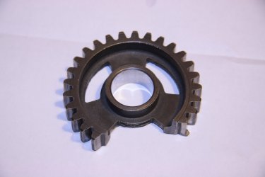
The gears are not made from castings..... the cut outs are stamped, the inner surface of these somewhat resembles a rough cast surface. 

piet
 
  This is the one that let go on my SFC, fortunately it only bent the layshaft, not the SFC specific mainshaft. Dosn't really tell much of a story, just let go whilst pulling hard out of a bend.


  Keith
 

Attachments

  • 006_1.JPG
    006_1.JPG
    84.5 KB · Views: 205
Rob if you do get an improved gear made we will be expecting you to give it a good test for a couple of thousand ks and maybe get a supply organised,who knowed if this is age related plus your balls to the wall style.Its good your fully testing the maque for us. :D
 
G'day Scrumpy.

Very interesting and erudite analysis there.  :D

I'm not sure I agree with your conclusion though. I remember a bit of materials science from my engineering studies, but I'm not a metallurgist so I could be talking through my arse. In fact it's quite likely...  ???

The inner edge of the oilway drilling is a sharp edge as you say, but that shouldn't be a stress raiser. When you look at it in section (which is exactly the view shown in the photo) that sharp edge is an external corner. It's generally only internal corners (or notches) that cause stress concentrations. The oil hole itself will be a stress concentrator, but not the edges of the hole.

Also, it looks lake a sudden failure to me, not a fatigue crack that's propogated slowly then let go. Fatigue cracks typically show as a smoothish fracture surface with concentric rings emanating from the starting point, a bit like the growth rings in a tree, or the ripples when you chuck a rock into a pond. The crack propogates a wee bit further with each stress cycle, creating the rings. When it gets to a point where the part can no longer carry the load, the remaining portion will break suddenly and show a rough "crystalline" surface. The fracture surface in Rob's shaft appears to be evenly rough looking, indicating a sudden failure.

Even though I don't think it's fatigue cracking, the failure mode can still be one that's developed slowly over time, such as work hardening that's caused the shaft to become more brittle over time. As it gets more brittle, it becomes less able to handle shock loads. It'll eventually get a shock that'll snap it like a carrot.

Not that any of this theory amnd conjecture makes any difference in the real world. The fact remains that the part wasn't strong enough and it fell apart. It needs to be made stronger somehow. It might be better to have several smaller diameter oilways instead of one big one if that's possible.

Cheers,
Cam
 
Robjota said:
If I sketch it up, would anyone be prepared to put in to CAD?

Yep. I can pretend to be a draughtsman and do a CAD drawing for you. Just email your scanned sketches to me:  cdouglas( at )netspace.net.au

I'm not sure about setting up a CAD file for loading into a NC machining process if that's what you had in mnd, but I can certainly draw a picture for you that will be compatible with AutoCad or other CAD software. If you don't have CAD software, I can send it to you as a pdf.

I think you can download free CAD viewing software. You can't actually draw anything, just look at a CAD file and make notes.

Cheers,
Cam
 
Hi Cam,

My materials studies where some time ago and not to any great depth. I did enjoy it though. So happy to accept your conclusions. I was tempted into the attic last night to dig around for some literature but I knew it was in the far corner under a pile of other stuff so did not bother.

Cheers Scrumpy
 
Dellortoman said:
G'day Scrumpy.

Very interesting and erudite analysis there.  :D

I'm not sure I agree with your conclusion though. I remember a bit of materials science from my engineering studies, but I'm not a metallurgist so I could be talking through my arse. In fact it's quite likely...   ???

The inner edge of the oilway drilling is a sharp edge as you say, but that shouldn't be a stress raiser. When you look at it in section (which is exactly the view shown in the photo) that sharp edge is an external corner. It's generally only internal corners (or notches) that cause stress concentrations. The oil hole itself will be a stress concentrator, but not the edges of the hole.

Also, it looks lake a sudden failure to me, not a fatigue crack that's propogated slowly then let go. Fatigue cracks typically show as a smoothish fracture surface with concentric rings emanating from the starting point, a bit like the growth rings in a tree, or the ripples when you chuck a rock into a pond. The crack propogates a wee bit further with each stress cycle, creating the rings. When it gets to a point where the part can no longer carry the load, the remaining portion will break suddenly and show a rough "crystalline" surface. The fracture surface in Rob's shaft appears to be evenly rough looking, indicating a sudden failure.

Even though I don't think it's fatigue cracking, the failure mode can still be one that's developed slowly over time, such as work hardening that's caused the shaft to become more brittle over time. As it gets more brittle, it becomes less able to handle shock loads. It'll eventually get a shock that'll snap it like a carrot.

Not that any of this theory and conjecture makes any difference in the real world. The fact remains that the part wasn't strong enough and it fell apart. It needs to be made stronger somehow. It might be better to have several smaller diameter oilways instead of one big one if that's possible.

Cheers,
Cam

Scrumpy

My fault for not explaining more about the broken mainshaft. it happened along with the 1st breakage of 4th gear.More damage was done that time and the missing portion of the gear (1/3 segment) was ejected out of the top of the crankcase, never to be found. The layshaft was also bent that time, as per Keiths comments on his SFC.
You can draw your own conclusions but mine were that the gear broke 1st and the section that jammed, cause the remaining damage as it forced its way out.

Coincidentally, this time, the top of the welded crancase has a dent and a leak where again it has tried and failed to come through, hopefully the mainshaft or layshaft haven't bent..

Piet, clearly I didn't know about the gear manufacturing process.... thanks for your input again..... Cam, thats a great offer, if the engineers need a drawing, I'd like to take up your offer, thank you, I have Autocad 2000 lt, cant use it but had it for reading drawings, when I had a proper job!
Greg, taken on board ... and Vince, you know I'll test it...next year hopefully with a higher mounted engine or something anyway. Cheers all !!!
 
Would the problem be contained by replacing the 4th gear set with modified parts, or would it then transfer the problem to the next weakest link?
I guess 3rd and 4th get the hardest time on track, but maybe it's only 4th that has this weakness?

All the boxes will be old and well-used by now.
At least the Team Corse close ratio set would be all-new. Maybe not stronger built, just less duty cycles.
 
Rob,

Are you certain the mainshaft snapped at the same time the gear gave up?

The mainshaft is not loaded torsionally in that area, it just rotates inside the 5th. gear sleeve.  As far as I can see, it snaps because of bending.... worn 5th. gear bearing and bushes and/or drive chain too tight.  Seen it several times, was able to trace it twice to the owner tensioning the chain to a point you could almost play a tune on it! :o  (I'm certain you don't do that, Rob.... but worth a check how the chain tension changes through the full range of suspension travel.  Your Wilbers(?) units will most probably offer more travel than the stock units, and if they are longer, the chain needs to be adjusted accordingly)

If the mainshaft snaps at that point, it is still supported by the 5th. gear bushes, the loose bit just floats around inside the gear.  Still strange it happens at all, the shaft is not normally overly stressed in this area.

piet
 
sfcpiet said:
Rob,

Are you certain the mainshaft snapped at the same time the gear gave up?

The mainshaft is not loaded torsionally in that area, it just rotates inside the 5th. gear sleeve.  As far as I can see, it snaps because of bending.... worn 5th. gear bearing and bushes and/or drive chain too tight.  Seen it several times, was able to trace it twice to the owner tensioning the chain to a point you could almost play a tune on it! :o  (I'm certain you don't do that, Rob.... but worth a check how the chain tension changes through the full range of suspension travel.  Your Wilbers(?) units will most probably offer more travel than the stock units, and if they are longer, the chain needs to be adjusted accordingly)
If the mainshaft snaps at that point, it is still supported by the 5th. gear bushes, the loose bit just floats around inside the gear.  Still strange it happens at all, the shaft is not normally overly stressed in this area.

piet

Hi Piet

No Im not certain, it was an assumption .....I made on the fact that the Lateral ? force placed on the shaft as the gear was driven through the crankcase. So yes, it could have already been broken..?

The shocks are standard length and are quite stiff so I couldn't comment on their travel but I do occasionally travel quite swiftly from standstill  :D so that would load the chain unduly and the mainshaft too ?
A cool outrigger bearing, that would be the way to go, I've seen one somewhere on a special framed Laverda....but I'll keep it simple
 
How about this were rideing round on 30 year old gear boxs ,older in many cases,if you replace one gear will it not be in the same wear rate as the others,better to replace the complete box ?
 
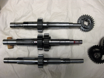
top to bottom

750SFC
close ratio triple
std triple

4th is bushless and 5th has 3 needle roller bearings
doesn't solve the sharp edges in the 4th gear windows
but certainly a much stronger shaft
 

Attachments

  • triple-mainshafts.gif
    triple-mainshafts.gif
    164.3 KB · Views: 40
Back
Top