
You are using an out of date browser. It may not display this or other websites correctly.
You should upgrade or use an alternative browser.
You should upgrade or use an alternative browser.
'77 triple poor running
- Thread starter Alexb83
- Start date


Dellortoman
Hero member
- Location
- Tasmania, Australia
Alexb83 said:Aside from the old reg/rectifier the old charging and ignition system is now off the bike.
If it's original, it may just be a rectifier without any voltage regulating function. If so, you'll need to replace it with a RR because the output from the Redax alternator will be greater than your old Bosch system.
The original rectifier is just a little black box, something like 60 x 40 x 10 mm with 4 spade terminals sticking out of it. (dimensions are an estimate - I don't have one to hand)
G
Grant
Guest
Red's system includes a new r/r.
Lee87H
Hero member
- Location
- Upstate New York USA
I'm at the same point as you in installing my Redax Ignition, but same as you the cold weather -32C is keeping me out of the shop for awile.Alexb83 said:Thanks everyone, after much filing 3.5 threads was enough to overcome the friction in the end.
Aside from the old reg/rectifier the old charging and ignition system is now off the bike.
I did have to dremel off one small nut from the old coil mount, but otherwise everything came off intact.
New coils are mounted, tomorrow should be sufficient time to feed through the stator/ignition wiring and get everything ready to try and set the timing on wednesday.
The limiting factor at the moment is the cold!
Alexb83
Full member
- Location
- Northumberland
I thought sub 10c was cold enough! Anyway, I managed to potter about in the garage a little this morning to try and make a bit of progress.
Those who have the Redax system already installed may be able to give me a steer here - Red's instructions are good but miss a few key bits of information (or rather they aren't quite paint-by-numbers enough for someone with my lack of aptitude).
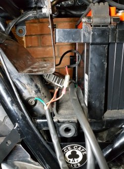
The ignition and alternator wires are all fed through the cable tunnel and dummy fitted to the reg/rectifier and to the ignition box in their approximate final positions, just so that we can test the ignition and look to set the timing. The stator is not yet mounted as I haven't been able to set the ignition timing.
The original rectifier has been removed, however I have retained the original red wire spade connection to the fuse box to attach the red/white from the new reg/rectifier.
The green wire from the rectifier is mounted to the frame ground at the rear mudguard (where the old rectifier used to connect to ground).
The red wire (sensing circuit) from the rectifier needs a connection to the ignition switch 'or to any live wire controlled by the ignition switch', however unless I'm much mistaken the nearest points where I could connect to the ignition are at the starter relay (the other side of the battery) or on the chocolate block up near the top of the frame. This seems like a long run and will require another wire spliced in - or am I being silly and I can just connect this to the positive side of the battery at the fuse box along with the red/white wire?
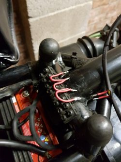
At the chocolate block, the only remaining connection after removing the old kit is a blue wire that runs down from the front end of the bike - this must be the connection for the ignition switch? (pictured, bottom left connection from the 'sat on the bike' perspective). I have a 3-wire daisy chain provided that needs a home, and also the broken wire in the wiring loom from the coils (which I assume wants to be connected to the ignition switch).
Those who have the Redax system already installed may be able to give me a steer here - Red's instructions are good but miss a few key bits of information (or rather they aren't quite paint-by-numbers enough for someone with my lack of aptitude).
The ignition and alternator wires are all fed through the cable tunnel and dummy fitted to the reg/rectifier and to the ignition box in their approximate final positions, just so that we can test the ignition and look to set the timing. The stator is not yet mounted as I haven't been able to set the ignition timing.
The original rectifier has been removed, however I have retained the original red wire spade connection to the fuse box to attach the red/white from the new reg/rectifier.
The green wire from the rectifier is mounted to the frame ground at the rear mudguard (where the old rectifier used to connect to ground).
The red wire (sensing circuit) from the rectifier needs a connection to the ignition switch 'or to any live wire controlled by the ignition switch', however unless I'm much mistaken the nearest points where I could connect to the ignition are at the starter relay (the other side of the battery) or on the chocolate block up near the top of the frame. This seems like a long run and will require another wire spliced in - or am I being silly and I can just connect this to the positive side of the battery at the fuse box along with the red/white wire?
At the chocolate block, the only remaining connection after removing the old kit is a blue wire that runs down from the front end of the bike - this must be the connection for the ignition switch? (pictured, bottom left connection from the 'sat on the bike' perspective). I have a 3-wire daisy chain provided that needs a home, and also the broken wire in the wiring loom from the coils (which I assume wants to be connected to the ignition switch).
Attachments
Alexb83
Full member
- Location
- Northumberland
nick7 said:Good for you in doing this...confess mine was fitted by Keith Nairn. Notice you had a ktm 690...wish i still had mine! If you are lucky Red might be along to answer your queries..mine was the Sachse system which i think is not now sold by Red?
The 690 was an awesome little bike. I moved jobs and needed to do a longer commute, so I opted for the adventure (which I love) but now that I'm not commuting any more I do wonder about chopping it in for something small and fun again.
Then again, the Laverda fulfils the fun quota (when I get it going again) and I only have room for 2 bikes, really, and having something you can tour on is nice.
Although it was an eye-opener going to Scrumpy's place and seeing exactly how many bikes you can fit in 10 meters squared.
I may try emailing red direct, but sooner or later he's going to redirect me to his spam folder


Rob
Hero member
- Location
- Midlands, UK
Alex - you may be guilty of trying to slavishly retain too much of your original wiring. Red's instructions are good and worth a careful re-read.
First comment - the green reg/rect wire needs a good solid clean connection to earth. Did you clean the paint off the frame under the allen bolt head at the rear mudguard? If not, please do so with a dollop of vaseline to prevent future rusting there.
The sense wire does want to be on a decent switched live supply...if you connect direct to the battery + you'll find a slow discharge will result which will eventually flatten the battery over a month or two. Been a long time since I played with 180 wiring, but there will be a switched live at the fusebox (black wire). You again need a good clean connection to avoid the regulator circuit seeing low volts and overcharging the battery. Starter relay won't do the job for you. Don't think there's anything on the choc strip either - that's ignition triggers and alternator output.
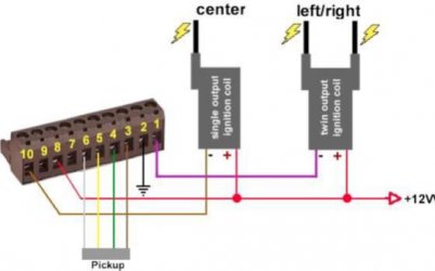
Mystified by your ref to a blue wire...can't see one on the CDI wiring diagram. Were the red wire loops part of the kit or original on your bike?
The 'broken' red wire (if part of the new kit's loom) is likely the 12v ignition switched feed to the coils which also needs to find its way to the Sasche box)
First comment - the green reg/rect wire needs a good solid clean connection to earth. Did you clean the paint off the frame under the allen bolt head at the rear mudguard? If not, please do so with a dollop of vaseline to prevent future rusting there.
The sense wire does want to be on a decent switched live supply...if you connect direct to the battery + you'll find a slow discharge will result which will eventually flatten the battery over a month or two. Been a long time since I played with 180 wiring, but there will be a switched live at the fusebox (black wire). You again need a good clean connection to avoid the regulator circuit seeing low volts and overcharging the battery. Starter relay won't do the job for you. Don't think there's anything on the choc strip either - that's ignition triggers and alternator output.
Mystified by your ref to a blue wire...can't see one on the CDI wiring diagram. Were the red wire loops part of the kit or original on your bike?
The 'broken' red wire (if part of the new kit's loom) is likely the 12v ignition switched feed to the coils which also needs to find its way to the Sasche box)
Attachments
Alexb83
Full member
- Location
- Northumberland
Hi Rob,
The wire loops were as provided by Red but arent mentioned in the instructions.
As it stands at the moment, the choc block retains only one (blue, i am sure but ill recheck in the cold light of day) wire at terminal 1 (bottom left) which comes out of the only wiring loom still running back from the front of the bike.
Everything from the old CDI system has now been pulled with the exception of the red wire that ran to the rectifier and now accepts the red/white from redax (suggested in the instructions)
The wiring loom from the coils connects to the ignition box, which also connects to the hall sensors.
The alternator connects to the reg/rectifier.
There are the two red wires conspicuously positioned as if they are intended to go into the chocbloc. But if they are to be switched by the terminal 1 connection, where should they connect?
The wire loops were as provided by Red but arent mentioned in the instructions.
As it stands at the moment, the choc block retains only one (blue, i am sure but ill recheck in the cold light of day) wire at terminal 1 (bottom left) which comes out of the only wiring loom still running back from the front of the bike.
Everything from the old CDI system has now been pulled with the exception of the red wire that ran to the rectifier and now accepts the red/white from redax (suggested in the instructions)
The wiring loom from the coils connects to the ignition box, which also connects to the hall sensors.
The alternator connects to the reg/rectifier.
There are the two red wires conspicuously positioned as if they are intended to go into the chocbloc. But if they are to be switched by the terminal 1 connection, where should they connect?

tom3c75
Hero member
- Location
- Cape Town South Africa
Is the blue wire not from the "Emergency switch relay", nr 32 on the CDI wiring diagram?
If so, this can be removed from the system when installing the new ignition system.
If so, this can be removed from the system when installing the new ignition system.
G
Grant
Guest
My recollection is the blue wire on the standard CDI loom comes from the kill switch (orange/white on BTZ looms).
Alexb83
Full member
- Location
- Northumberland
Grant said:My recollection is the blue wire on the standard CDI loom comes from the kill switch (orange/white on BTZ looms).
Looking back through my WIP photos, terminal 1 was shared - dark blue and light blue.
The light blue is still connected.

Alexb83
Full member
- Location
- Northumberland
Thanks Red,
On Red's directions, I have used the light blue (kill switch) wire and the provided bridge in the terminal block.
From there, I can connect the sensing wire on the reg/rectifier, the supply to the coils and the return to the ignition box.
The red/white wire from the reg/rectifier, which is the return to the battery, is connected at the fuse box.
Grounds from the ignition box and the reg/rectifier are to the frame ground on the back of the battery tray.
Multimeter shows good voltage on the battery, to the coils, and to the sensing wire terminal.
Sense checking all the coloured wires on the connections to/from the ignition box shows they are all correct.
Now all that said, I went to look at setting the timing - turned on the ignition and rotated the timing rotor on the crank.
No signs of life from the sensor PCB (the LED is supposed to light).
Any thoughts?
On Red's directions, I have used the light blue (kill switch) wire and the provided bridge in the terminal block.
From there, I can connect the sensing wire on the reg/rectifier, the supply to the coils and the return to the ignition box.
The red/white wire from the reg/rectifier, which is the return to the battery, is connected at the fuse box.
Grounds from the ignition box and the reg/rectifier are to the frame ground on the back of the battery tray.
Multimeter shows good voltage on the battery, to the coils, and to the sensing wire terminal.
Sense checking all the coloured wires on the connections to/from the ignition box shows they are all correct.
Now all that said, I went to look at setting the timing - turned on the ignition and rotated the timing rotor on the crank.
No signs of life from the sensor PCB (the LED is supposed to light).
Any thoughts?
Dellortoman
Hero member
- Location
- Tasmania, Australia
Is the kill switch on?
Alexb83
Full member
- Location
- Northumberland
Dellortoman said:Is the kill switch on?
:
 The kill switch was not killing
The issue turned out to be the alignment of the magnets and the hall probes - now sorted.
I'll work on setting timing later today, but it'll probably get revisited down the road for accuracy when I've actually made a degree wheel out of the old alternator rotor hub
Dellortoman
Hero member
- Location
- Tasmania, Australia
Making a degree wheel from the old alternator rotor is doing it the hard way. Means you have to swap rotors to check timing. I presume you have the 2 different pullers needed for that. To ensure the TDC mark is in the right place, you'll need a degree wheel. Kind of a catch 22 there.
I've made degree wheels out of old CDs that cost nothing and work well enough (can time stuff to better than 1 degree accuracy).
I drew up a 360? protractor on CAD to the diameter of a CD. I've attached pdfs here. 2 versions with different cam timing marked - dial in your cams while you're at it.
All you need to do is print the one you need, cut it out, glue it to an old CD (preferably rap music - one less of those in the world has got to be a good thing), bore the centre hole to suit whatever you want to fit it to, and you're done.
For the Laverda, a 22mm dia centre hole will fit the thread for the alternator rotor nut. Remove the nut, slip the degree wheel on and replace the nut. You can rotate the degree wheel to align with TDC before nipping up the nut to lock it in place.
Series 1 engines have a dry (no oil) alternator case so you can run the engine and strobe the degree wheel to make sure you have the correct base advance programmed into your ignition. Setting the base advance with the little LEDs will get you pretty close, but it's difficult to get it spot on. It could end up a degree or two either way.
The way I do it is to program the Ignitech with 0? advance throughout (base advance as well as the advance curve). Start the engine and use the strobe to see where on the degree wheel it's firing. That's the base advance to enter into your program. You may have to give it a bit of throttle to settle the revs for a clear reading because it jumps around a bit at idle. Once you've confirmed the base advance, you can load up the rest of your advance map.
I've made degree wheels out of old CDs that cost nothing and work well enough (can time stuff to better than 1 degree accuracy).
I drew up a 360? protractor on CAD to the diameter of a CD. I've attached pdfs here. 2 versions with different cam timing marked - dial in your cams while you're at it.
All you need to do is print the one you need, cut it out, glue it to an old CD (preferably rap music - one less of those in the world has got to be a good thing), bore the centre hole to suit whatever you want to fit it to, and you're done.
For the Laverda, a 22mm dia centre hole will fit the thread for the alternator rotor nut. Remove the nut, slip the degree wheel on and replace the nut. You can rotate the degree wheel to align with TDC before nipping up the nut to lock it in place.
Series 1 engines have a dry (no oil) alternator case so you can run the engine and strobe the degree wheel to make sure you have the correct base advance programmed into your ignition. Setting the base advance with the little LEDs will get you pretty close, but it's difficult to get it spot on. It could end up a degree or two either way.
The way I do it is to program the Ignitech with 0? advance throughout (base advance as well as the advance curve). Start the engine and use the strobe to see where on the degree wheel it's firing. That's the base advance to enter into your program. You may have to give it a bit of throttle to settle the revs for a clear reading because it jumps around a bit at idle. Once you've confirmed the base advance, you can load up the rest of your advance map.
Attachments
Alexb83
Full member
- Location
- Northumberland
I ended up setting the timing with a screwdriver, a socket and a lot of patience.
One backfire, a few seconds only running on 2 cylinders and then it settled in.
Thanks to A14RGS and to Scrumpyjack for their emotional support.
Alan is of the opinion that it is running rich, and there is reason to suspect that a previous owner had the jetting set up wrong (i.e. for a Jota, rather than for a 1200 with 4C cams and HC pistons)
The crank end nut initially didnt feel like it had much clearance to the outer alternator cover - although it is on as tight as it will go. The cover has fitted back flush.
Wiring to tidy up tomorrow and regulator/rectifier to mount properly.
After that the next step is as you say to sit and do some fine tuning with the laptop and strobe light.
One backfire, a few seconds only running on 2 cylinders and then it settled in.
Thanks to A14RGS and to Scrumpyjack for their emotional support.
Alan is of the opinion that it is running rich, and there is reason to suspect that a previous owner had the jetting set up wrong (i.e. for a Jota, rather than for a 1200 with 4C cams and HC pistons)
The crank end nut initially didnt feel like it had much clearance to the outer alternator cover - although it is on as tight as it will go. The cover has fitted back flush.
Wiring to tidy up tomorrow and regulator/rectifier to mount properly.
After that the next step is as you say to sit and do some fine tuning with the laptop and strobe light.