Advice on original connectors and wiring

Franc

New member
Location
UK - Midlands
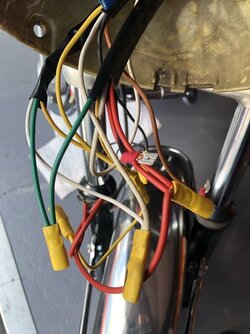
Morning all - Decided to tidy up all the wiring on my 73 SF as it is a mess have already found a potential serious issue under the tank, and the horn intermittently acts as a kill switch. There was a full bowl of Spaghetti in the headlight joined, taped, crimped and scotch-locked not to mention a spare live feed floating about. Things like the I instrument backlights only working on low beam not high presumably Not a stock feature.....

01F46D97-1112-4EE2-AB52-841B957F2DD1.jpeg

I have a lot of experience with replacing and tracing on auto electrical faults so no issues with the doing side of this. But does anyone have any pictures of an original setup, did Laverda use the brass type bullets with black or clear connectors in the early 70s, or spades? I’d also appreciate seeing how the fuse box looked under the side panel or at least how someone else has done it on a tidy bike.

For safety and reliability this needs doing so any help with getting close to original greatly appreciated. I’m also going to fit a set of CEV indicators so interested to know where the flasher relay was mounted on bikes that had them.

Thanks
Franc
 
What type of headlight, instruments and switchgear? My experience is mostly with triples, the earlier of which usually use two strips of 1/4" spade terminals for general connections and power distribution. That arrangement in yours is obviously not original.
I always thought the bowl of spaghetti was an abomination but after having to rebuild one it actually makes a reasonable degree of sense. It allows a really small wiring harness and all your connections are within the most weatherproof part of the bike, so it's not all bad.
If everything is original and in decent order, the biggest issue in my experience is the lack of a dedicated ground wire up to the headlight bowl, relying only on grounding through the steering head bearings. The first thing I do is run a decent size ground wire from the main frame ground point near the battery, stop off at the coil grounding point, then run it into the headlight and distribute grounds properly in there. Solves a lot of the problems.
Someone with a matching year model 750 will no doubt be along shortly to provide a picture to guide you how it should be.
Cheers
Steve
 
Thanks for that Steve - it has ND clocks and as i'm adding indiators i've got some old but nice ND switches in good order. I'll definitely start with the ground wire so theres a decent negative feed, the actuall wiring that's there is not to bad though I will get rid of the length of 3 core mains flex that's been added.. I was looking on the Laverda parts site and the list relays for such as the horn and the lights were these standard? easy enough to add them and kinder on the switchgear?

Will put a few photos up as I go ....
 
My 1973 SF1 had all the wiring in two strips of 6.3mm spades (as per Steve's description), but under the tank, not in the headlight, which was the chrome CEV unit with nothing inside other than the four wires for the headlight globe and parker. Definitely add relays (headlight) and it helps to have one as the main power connection from battery to fuse box for power outlets, bypassing the ignition switch completely for high current duties. Relays are your friend!

You can definitely clean up the system and reduce unwanted doubling up. Definitely need a horn relay (std it's attached to the horn bracket). If switching from Lucas to ND be aware that the horn button on the ND simply earths the relay circuit - took my green youth mind ages to sus why it kept blowing the main fuse every time I pushed the horn button!!

I personally like the under tank location of the SF1 - once tucked away with some cable ties it's set and forget. Fuse box could well do with upgrading to blade type - you can see where the orig mounted by the two holes on the metal bracket - Lucas relay sits in a little rectangular tin cradle that's also bolted to the bracket, somewhere near the starter relay. I'd just use any aftermarket digital relay. you can mount them in foam tube anywhere under the sidecover.

Someone will have pics - mine was modded and improved decades ago.
 
Thank you for the info that’s really useful - my SF has no relays which I thought was a bit odd even though the wiring is a good weight, the horn button is going to erode away as it draws a good few amps. The power comes into the regulator from the generator then off to the battery that all tests out ok running. I’ll get a couple relays I presume a couple of Lucas will do the job?

Cheers
 
Horns were always powered through relays on the twins, at least the 2-tone Fiamms. Lots of options to clean/tidy things up, I've replaced the strips of spade connectors with the later type compact connectors on my GTL. Creates loads of free space both under the tank AND in the headlight bowl, without sacrificing any legal requirements. Does mean making a loom from scratch though.

In any case, those gruesome coloured squash connectors have no business being on a motorcycle... failures waiting to happen! Crimping with a good quality crimping tool can actually turn out to be fun! Wiring a bike from scratch has something very soothing about it, good music and a beer or 3 can be a great help.

piet
 
Totally agree, Piet. I bought a really good quality crimper and wire stripper and never looked back. Those plastic insulated horrors elicit instant dread in me when I see them on ANY bike I work on. Pure evil.

I've recently had trouble sourcing the excellent Utilux heavy brass spade terminals I've used for years but run out of. Unfortunately many auto elec suppliers now only offer the much thinner (read 'fragile' on a vibish Laverda) variants - I've used some but want to replace them - it's not so much that they might break, but they simply don't connect with anywhere near the pressure of the heavier ones once pushed onto the male connector in the strip blocks. I'm a stickler for 'do it right, do it once' with electrics - how to spoil a good ride or long tour, having totally avoidable electrics gremlins.
If I wasn't using an additional three relays (ignition, headlight H & L) I could probably have reduced the SF1 strip connectors by well over 50%. As it is I run them no longer than 5 connectors long, four in total.
 
I re-did my 75 SF-2 with the two 6.3 mm strips like Pirahna describes. My first 1975 SF-2 had that system , but with a rubber
enclosure, if memory serves me well.
It was just about a complete re-wiring. The P.O made a mess of it..
I also added a new blade type fuse box,to replace the ceramic fuses and some mini relais for horns and lights.
Still not totally happy.
Have you got any pictures of your setup Piet ?
What kind of crimper do you use Piranha ?
 
Thanks to everyone for your input just sketching up a diagram, but in essence all the crimpy squash type connectors go. I have 4 new Lucas relays and a flasher unit I got a while ago NOS From the 70s when it was proper - which will allow me to get the lighting, horn, and the coils on good feeds with the handlebar stuff just powering the relays. Is the the coil power worth taking away from the ignition switch and onto a relay or am I over complicating ? I suppose I should have checked the voltage at the coils before I started dismantling.

Anyway off to get some bits when the shops open

Franc
 
Depends mainly on what type switch you're using. I rebuilt my GTL in 1994, using as many original or NOS parts as possible. I was lucky to be able to pick what I needed from the Moto Witt stock, most OE parts were still readily available. The ignition system is powered directly from the old ND ignition and kill switch, no issues at all. The repro items available today have trouble with coping with twin Voxbell horns on the triples, I wouldn't trust it as far as I could throw it! Things look brighter with the Bosch switches, these are vey sturdy and tend to last forever.

piet
 
I've replaced the strips of spade connectors with the later type compact connectors on my GTL. Creates loads of free space both under the tank AND in the headlight bowl, without sacrificing any legal requirements. Does mean making a loom from scratch though.


piet
Got a pic and info of these connectors Piet?
 
I would have liked to go straight to Lucas but
I already have a set of the good CEV repros and the rear end mounting stem - I’m doing a lot of work with the wiring and relays etc. So I’m going with the CEVs but will change them in phase 2 I’m sure the CEVs will sell on eBay.

I love the idea of rivet counting but I’m rapidly leaning toward period feel with practicality and reliability. Had lots of good advice and I can already see the improvement of not having all the scotchlocks and squash crimps.

Franc
 
Got a pic and info of these connectors Piet?
I used H-D connectors, as used universally in their 1990's models. Cheap, well made and readily available at the time. Very similar to those used in part on the RGS and SFC 1000. White plastic with round contacts. They have very cunning internal bridging pieces, making multiple cable loops unnecessary. Pics next week, don't have the bike at home at the moment.

Quentin, at least Germany didn't get Lucas indicators, CEV here. Seems it was often up to the importer to fit whatever they chose.

piet
 
thats something important that I had not thought about my sf was first registered in the Netherlands so was probably on CEVs me being in the uk I have been considering other SF1s ive seen in the here as being correct

thanks piet
 
Innaresting re CEV vs Prince of Darkness.

Piet, I really like the sound of those bridged connectors - I ended up doing the piggyback thing for power takeoffs to various places (headlight relays, LH switchblock etc). Would work for earths as well. I'm sure I can do better. Once my harness is in place I can upgrade connectors when time permits.
 
Sorry for the crap quality, only had my crappy phone with me. All that's left of the original rats' nest, flasher is located under the side panel, headlight relays under the tank, next to the coils. The bridging piece can be seen on the bottom row of connecting pins. This little gizmo conects 6 wires in all.

piet
 

Attachments

  • DSC_0274[1].jpg
    DSC_0274[1].jpg
    128.9 KB · Views: 80
  • DSC_0275[1].jpg
    DSC_0275[1].jpg
    97.9 KB · Views: 80
Back
Top