
You are using an out of date browser. It may not display this or other websites correctly.
You should upgrade or use an alternative browser.
You should upgrade or use an alternative browser.
Atlas Questions
- Thread starter Vince
- Start date
Big Atlas day. It was finaly time to take the bike to Hand Made Fibreglass and look for a slightly bigger screen and then look at a suitable set of Bark Busters that would fit on the limited Handlebar space, who knew there are lots of different lengths and bends of Bark Busters. It was pretty close to the same trip I made to Eastern Creek to watch the Redax Race Team is I didn't expect any dramas, stupid me. So after a 40k M2 Expressway run in a pretty bad westerly headwind I arrived at the screen place. I lucked out, they had a Suzuki Something screen mould that will work great, I will pick it up in a week or so. Then off to the Bark Busters place where they found a set that will go close, I hope. So that's about an hour on expressways cruising at 120ks, I go to leave the Bark Busters place and the bike keeps stalling. YEP, THE BLOODY IDLE JETS ARE BLOCKED AGAIN. So that's 2 out of the 3 longish rides I have done since Christmas and its arrival in the country has resulted in blocked idle jets. The tank is as clean as a whistle, there are clean filters in both fuel taps and a clean filter where the hoses attach to the carb. But I do have a plan. My bike has the original long-type idle jets not available in Oz but you can get them from England, they look like a shorter version of an Emulsion Tube, approx 30mm long with a long thin section with multiple cross drillings. They have been superseded by the new typical-looking 5mm x 5mm idle jets. Maybe these shorter jets don't block so easily, it's worth a try. This blocked idle jet thing appears pretty common on Side Draught and also on Down Draught Dellorods and Webbers especially when used on VWs in off-road racing. Nothing is getting past the air filter, I would love to find a reason why this crap gets into the bowl in the first place. It sees Zero dusty dirt roads so where is it coming from? Carbs are clean the last time I looked. BTW it went over the local Tips weigh Bridge heading home and with I guess 3/4 of a full tank it weighs 200kg.
While waiting for the new idle jets to turn up from Melbourne I decided after not having enough room on the handlebars to mount the inner Barkbuster connections I needed to modify both the width and height of the Navigation tower so I could reach the ignition key easier and get a better view of the instruments. So back to stage one on mounting that gadget. It's now 15mm narrower on each side and will end up 30 or 40mm higher. Hope that doesn't affect the mounting of the higher windscreen coming soon that will bolt to and be supported by the Navigation Tower.

Good to hear you are getting it sorted.. say where were you last Saturday were you not coming with us for breakfast, anyways guess you were busy now please do remember that if you go too high with the tower that you may well need to chat with CASA after all your area is in one of the flight paths rightWhile waiting for the new idle jets to turn up from Melbourne I decided after not having enough room on the handlebars to mount the inner Barkbuster connections I needed to modify both the width and height of the Navigation tower so I could reach the ignition key easier and get a better view of the instruments. So back to stage one on mounting that gadget. It's now 15mm narrower on each side and will end up 30 or 40mm higher. Hope that doesn't affect the mounting of the higher windscreen coming soon that will bolt to and be supported by the Navigation Tower.
 think

 perhaps you may need some type of beacon for it

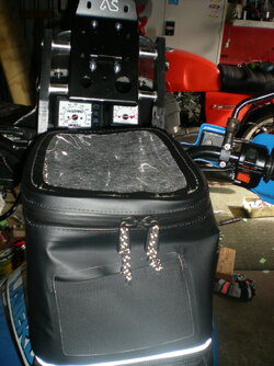
Ever heard of old school maps in the tank bag window just a suggestion

Carb job No3 I think. Getting good at accessing the jets, so today I pulled and cleaned the idle and mains and as usual, found nothing obvious. I tried the Brake bleeder to vacuum anything out, couldn't feel much suck on the hose. So I gave it a good going over that that and compassed air and Nulon Carby cleaner, let it sokes for a good hour and did it again. The new slightly richer idle jets replacing the superseded versions, 52 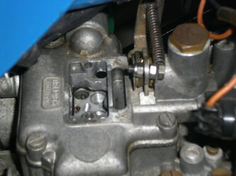 with a 58. I took a pic of these new and old jets and I hope with the new on
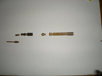 es not having the super long end they won't block as easily. The long thin part bottom left is the original idle jet its really tiny hole extends right through it, and above it is the new small more typical idle jet. To the right of that is the idle jet I guess the emulsion tube the idle jet pushes into it, and the main jet does the same to its emulsion tube. It took some adjusting on the carb idle screw but it starts and ticks over nicely. Hope it stays that way. BTW the jet on the right is the main jet and the Emulsion tube behind it.
with a 58. I took a pic of these new and old jets and I hope with the new ones not having the super long end they won't block as easily. The long thin part bottom left is the original idle jet its really tiny hole extends right through it, and above it is the new small more typical idle jet. To the right of that is the idle jet I guess the emulsion tube the idle jet pushes into it, and the main jet does the same to its emulsion tube. It took some adjusting on the carb idle screw but it starts and ticks over nicely. Hope it stays that way. BTW the jet on the right is the main jet and the Emulsion tube behind it.
Last edited:
Those old idle jets are 3 times longer than the new type, that's got to be a restriction and block much easier with that hole like the dia of a human hair and originally 35mm long and is now 5mm long. I did notice a slightly lumpier idle note with the 58 jets up from 52 but it revs just as quickly and easily. I need to go back to the Fibreglass place to get the new slightly taller screen drilled and fitted next week so that will be a good test ride.

Dellortoman
Hero member
- Location
- Tasmania, Australia
Interesting looking carby. I've never had any experience with those DCOE type of carburettors. Never owned a car with them. I guess they made it that way for good access to the jets when it's installed in a car.
Soon I will be wiring and fitting a combination Volt meter with ambient temperature and clock functions to the dash. Being green smoke challenged I want to NOT have this compromise the engine spark, from what I can see it has 3 wires red I guess is power black is earth and green is who knows. Its incomprehensible wiring diagram says verbatim quote, Red wire locks the anode before, Black wire after locking the anode, green wire Ground wire. That's what I see coming out of the gadget. Then it shows an ignition keyed switch picture with quote, Red wire locks the anode before, in parenthesis {Power supply cathode}, black wire, After locking the anode, in parentheses, {Switch after locking the anode}, Green wire ground wire, in parenthesis, {Power supply cathode}. The ignition switch is hard to get at, is it possible to tap this into the bike wiring somewhere and not compromise the engine spark or flatten the battery? I guess I need switched power, horn or blinkers maybe? The latter is pretty easy to get at and hopefully gremlin safe. Anodes and cathodes, who knew It also chrome plates stuff as well?
No 3c for Walca, better on the Oxley. Atlas for rego day is the plan. Been fabbing pannier mounts for both bikes, much harder than I expected. Heading out your way to Handcraft early next week for a slightly bigger screen on the Atlas. It's made but needs fitting, be a good test for the new short idle jets, fingers crossed it goes well. Shouldn't you be halfway to Queensland?

Andy J
Hero member
- Location
- Isle of Man
I’m glad you‘re making progress Vince with the improvements to the bike.
As for my Mk3, it let me down yesterday with an effing front tyre puncture on my way back from a wasted trip to try and open an executor’s account at a local branch of HSBC.
The only up side of a very frustrating morning was that I had safely negotiated the 70mph dual carriage way and had slowed to under 40 when I realised something was amiss with the front end; and was less than a 20 minute walk to collect my van to go and retrieve the crippled machine.
As for my Mk3, it let me down yesterday with an effing front tyre puncture on my way back from a wasted trip to try and open an executor’s account at a local branch of HSBC.
The only up side of a very frustrating morning was that I had safely negotiated the 70mph dual carriage way and had slowed to under 40 when I realised something was amiss with the front end; and was less than a 20 minute walk to collect my van to go and retrieve the crippled machine.
It's so much work doing estate stuff, been there. Did you find the cause of the puncture, its usually rears? How's it running and starting with the 2 separate bike-type carbs, Mikunis I think you said? Thinking about that Volt gauge wiring, it's got a clock that needs constant power so that's why there are 2 power connections, one to run the clock permanently but probably not lit up and one switched power to run the volt mitre and ambient temp.
Dellortoman
Hero member
- Location
- Tasmania, Australia
Soon I will be wiring and fitting a combination Volt meter with ambient temperature and clock functions to the dash. Being green smoke challenged I want to NOT have this compromise the engine spark, from what I can see it has 3 wires red I guess is power black is earth and green is who knows. Its incomprehensible wiring diagram says verbatim quote, Red wire locks the anode before, Black wire after locking the anode, green wire Ground wire. That's what I see coming out of the gadget. Then it shows an ignition keyed switch picture with quote, Red wire locks the anode before, in parenthesis {Power supply cathode}, black wire, After locking the anode, in parentheses, {Switch after locking the anode}, Green wire ground wire, in parenthesis, {Power supply cathode}. The ignition switch is hard to get at, is it possible to tap this into the bike wiring somewhere and not compromise the engine spark or flatten the battery? I guess I need switched power, horn or blinkers maybe? The latter is pretty easy to get at and hopefully gremlin safe. Anodes and cathodes, who knew It also chrome plates stuff as well?
Sounds like the instructions have been translated from Chinese, via Swahili to English by someone who speaks none of those languages.
I don't think you're over-thinking it at all. You need to know where to connect each of the 3 wires. I presume there's no wiring diagram.
Clock, thermometer and voltmeter on the same power supply seems incompatible to me. A clock needs to be powered all the time so as not to lose its time setting. The thermometer and voltmeter only need to be powered when you're looking at the dash (ie. when the ignition is turned on and you're riding the bike). So, I'm guessing the red and black wires are separate 12V supplies. One full-time and the other only when the ignition is on. Green is unambiguously ground, earth (or 0V as sparks guru John prefers).
From the gobbledygook instructions, I'd guess that "locking the anode" is some crazy translation of "ignition switch lock"). So "Red wire locks the anode before" means it should be connected to continuous +12V, before the ignition switch. So that wire must be the clock power supply.
"Black wire after locking the anode" is connected to a switched +12V supply, after the ignition switch. So that one would be for the voltmeter and thermometer.
The best way to find out for sure is to hook the leads up to a battery and see what happens. You know that the green wire is negative, so you just need to alternately connect the red and black wires to a positive terminal and see what part of the display lights up. For the purposes of experimentation, many of these little electronic doohickeys will work perfectly OK on a little 9V dry cell battery, so you can do it in the comfort of your home before taking it out to the shed to fit it on the bike.
For example, I use a dummy harness for Ignitech modules powered by a 9V battery for pre-programming the units before they get fitted to a bike. Very handy if it's a customer's bike and the ignition unit is to be mailed to them.
No wiring diagram, just pictorials with that quoted blurb. Makes sense, these wires are tiny. I don't want to muck about with the wiring at the key as it's a buggar to get at so any guess where taping in would be good. I am hoping the left front blinker would have both switched and permanent power. If no permanent power there I suppose I could run a wire directly to the battery with an inline fuse. What draw would a clock have, I doubt it's illuminated all the time, there is a button on the gadget, powered yes lit up no, it's a typical smallish dirtbike battery.

Rob
Hero member
- Location
- Midlands, UK
Picking up a voltmeter feed (switched live) can cause heartache if it's not a clean feed. If you use the indicator supply then the load / voltdrop will affect readings, particularly when the indicators flash! Same is true for most other likely feeds. You need to get as close as possible to the main ignition supply, downstream of the switch.
I'd also be wary of hooking up a standing load like a clock. Even if it's just a milliamp or two, your small battery will suffer unless you're in the habit of hooking up a battery charger - drain at 1.5mA will be an amphour (1AH) every month
I'd also be wary of hooking up a standing load like a clock. Even if it's just a milliamp or two, your small battery will suffer unless you're in the habit of hooking up a battery charger - drain at 1.5mA will be an amphour (1AH) every month

The Sock
Hero member
- Location
- London, England
Doesn't your Satnav show the time, Vince?
Yes, it does, but it's tiny. It's approx 2.5mm in the top corner. I couldn't see it unless its right in my face. Nomaly who cares what time it is but we have speed cameras in school zones that go from 60 or 50 to 40ks at certain times. That battery drain kills the clock idea, my shed has no power so running a trickle charger doesn't happen and my bikes can sit around for weeks between rides.
Dellortoman
Hero member
- Location
- Tasmania, Australia
I am hoping the left front blinker would have both switched and permanent power.
Nah. No go with the indicator. You should be able to find both switched and permanent power at the fuse box.
I don't reckon the clock will be a serious drain on the battery. Plenty of cars have clocks in them, but with a cheapo item of dubious efficiency, you never know. If you'd rather not use the bike's power supply to permanently power the clock, use a 9V battery. The clock should work but the display mightn't be as bright as it would be on 12V.
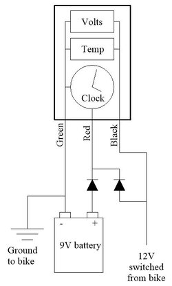
If you're really clever, you could wire it via a couple of diodes as shown below so it has 12V (full brightness) while the ignition is on, and a 9V battery as a backup to maintain its memory while the bike is parked. Tuck the 9V battery away somewhere that you can easily get at it when it needs to be changed. With this setup, you'll only need to find a 12V switched supply. No need to delve into the bike's wiring for a permanent 12V supply (the 9V battery does that job). I'd guess the 9V battery should last a year or two. Think of how long the pissy little battery lasts in a digital watch.
Last edited: