You are using an out of date browser. It may not display this or other websites correctly.
You should upgrade or use an alternative browser.
You should upgrade or use an alternative browser.
Building a race bike
- Thread starter julian
- Start date


Fantastic guys
So far mine are, 13.50kg with studs.
Little bit more to go to machine out the primary drive idler bearing and loose some weight from it (rough placed and braced at the moment) then have a few more ideas to loose a few more grams. Already pleased with that though. Big thanks.
Jules
So far mine are, 13.50kg with studs.
Little bit more to go to machine out the primary drive idler bearing and loose some weight from it (rough placed and braced at the moment) then have a few more ideas to loose a few more grams. Already pleased with that though. Big thanks.
Jules


Laverda SF
Hero member
A race bike is a bike that YOU personalize and can handle best then more powerful bikes.

piranha-bro2
Hero member
- Location
- Melbourne
julian said:Little bit more to go to machine out the primary drive idler bearing and loose some weight from it (rough placed and braced at the moment)
Jules
What's the primary drive idler bearing, Julian? Are you fitting some sort of primary chain support between the clutch sprocket and primary?
And yes, some pics of your progress would be great!
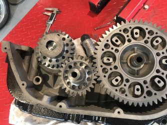
Gear drive as it is at the moment,
Still need to machine the bearings etc for it, at the moment the housings are there and the shaft is a light press fit.
This will change to a needle roller inboard with a hollow hardened pin pressed into the gear and another needle in the outrigger.
So far and with the primary crank gear only partially machined we are1150g 900g lighter than the chain and sprockets. (more accurate scales)
Will take more pictures later today after more playing.
Now with a little more fettling at 13.40kg maybe another 30g to go but I think without going totally mad, we are there for the cases now.
Taken some pics and will download on monday.
Cheers,
Julian
Still need to machine the bearings etc for it, at the moment the housings are there and the shaft is a light press fit.
This will change to a needle roller inboard with a hollow hardened pin pressed into the gear and another needle in the outrigger.
So far and with the primary crank gear only partially machined we are
Will take more pictures later today after more playing.
Now with a little more fettling at 13.40kg maybe another 30g to go but I think without going totally mad, we are there for the cases now.
Taken some pics and will download on monday.
Cheers,
Julian
Attachments

steph
Hero member
- Location
- Torgny, Belgium
Fantastic primary upgrade !


Dellortoman
Hero member
- Location
- Tasmania, Australia
Will be interesting to hear it running under load. Those spur gears will make a bit of noise. Will probably whine like a siren at high revs, that's if you can hear it over the exhaust.

chrisk
Hero member
- Location
- Brisbane, Australia
The bar has been raised ..... way high.
piranha-bro2
Hero member
- Location
- Melbourne
Full-blown remanufacture! Wild stuff! Chapeau.
Dellortoman
Hero member
- Location
- Tasmania, Australia
chrisk said:The bar has been raised ..... way high.
Let's hope it doesn't come crashing down.

I was trying to figure out the bearing load on that idler, but need to know the maximum torque produced by the engine to do that.
How much torque is a hotted-up, short stroke 750 likely to produce at the crank?
chrisk
Hero member
- Location
- Brisbane, Australia
Dellortoman said:Let's hope it doesn't come crashing down.
I was trying to figure out the bearing load on that idler, but need to know the maximum torque produced by the engine to do that.
How much torque is a hotted-up, short stroke 750 likely to produce at the crank?
Don?t forget he is putting a outrigger in the primary case, as well.
Not that far removed from the Redax output shaft outrigger concept.
Well executed, and I think Julian is on a winner. Very clever, IMHO.

Jo
Hero member
- Location
- Cologne, NRW Germany
Dellortoman said:Let's hope it doesn't come crashing down.
I was trying to figure out the bearing load on that idler, but need to know the maximum torque produced by the engine to do that.
How much torque is a hotted-up, short stroke 750 likely to produce at the crank?
Due to the short stroke layout the torque should be shifted slightly to the upper speed range - which would rather favor the design of the
bearings. 100 Nm plus safety margin should be ok IMHO. I can't wait to hear this SFC screaming in real life someday ...
8)
Dellortoman
Hero member
- Location
- Tasmania, Australia
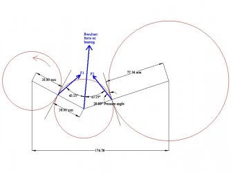
OK, I did a little vector diagram of forces. Assuming engine torque of 100 Nm, the tangential force at the PCD of the crank gear is around 2600 N.
There's a similar force on the clutch gear, so the force on the idler bearing is the resultant of those two gear tooth forces.
After more assumptions (like a guestimate of 20? pressure angle on the gear teeth, and using the dimensions of the triple primary drive because I don't have the twin info) and bit of geometry and head scratching, I worked out that the resultant radial force on the idler bearing is about 4080 N (416 kg), trying to jam the gear upwards between the crank and clutch gears. Note that it's an idler, so there's no torsional load on the shaft, and with spur gears (as opposed to helical) there's no axial load either.
I dunno whether my calculation is actually correct because I just came up with the whole theoretical analysis myself in about 10 minutes. A gear train expert might have a better way of doing it, but my sums should be somewhere in the ballpark. I'd be interested to know whether Julian has done a similar calculation, and if so, what he came up with.
But all of that is assuming a constant torsional load at the crankshaft of 100 Nm. In reality there will be some shock loading through the drive train caused by gear changes, rear wheel making or breaking traction, pulling wheelies, snatching of the rear chain during suspension movement, etc. Some of the shock loading would absorbed by the cush drives in the rear hub and clutch, but there will still be some portion of the shocks getting through to the primary drive. So I'd be allowing a reasonably generous safety factor in the design of the bearing supports and the selection of the bearing itself.
When the throttle is closed and the clutch is driving the engine on overrun, the forces are reversed (trying to spit the idler gear out the bottom of the primary case) but they'll be a lot less than when under power because engine braking is effect is a lot less than the power output at full throttle.
There's a similar force on the clutch gear, so the force on the idler bearing is the resultant of those two gear tooth forces.
After more assumptions (like a guestimate of 20? pressure angle on the gear teeth, and using the dimensions of the triple primary drive because I don't have the twin info) and bit of geometry and head scratching, I worked out that the resultant radial force on the idler bearing is about 4080 N (416 kg), trying to jam the gear upwards between the crank and clutch gears. Note that it's an idler, so there's no torsional load on the shaft, and with spur gears (as opposed to helical) there's no axial load either.
I dunno whether my calculation is actually correct because I just came up with the whole theoretical analysis myself in about 10 minutes. A gear train expert might have a better way of doing it, but my sums should be somewhere in the ballpark. I'd be interested to know whether Julian has done a similar calculation, and if so, what he came up with.
But all of that is assuming a constant torsional load at the crankshaft of 100 Nm. In reality there will be some shock loading through the drive train caused by gear changes, rear wheel making or breaking traction, pulling wheelies, snatching of the rear chain during suspension movement, etc. Some of the shock loading would absorbed by the cush drives in the rear hub and clutch, but there will still be some portion of the shocks getting through to the primary drive. So I'd be allowing a reasonably generous safety factor in the design of the bearing supports and the selection of the bearing itself.
When the throttle is closed and the clutch is driving the engine on overrun, the forces are reversed (trying to spit the idler gear out the bottom of the primary case) but they'll be a lot less than when under power because engine braking is effect is a lot less than the power output at full throttle.