Horn wiring and horn repair

Great job Paul

I doubt anyone who has had to deal with Laverda electrics is laughing but cheering. Even guys who do a lot of wiring take time to do it right with correct connectors and heat shrink.
Just one job left,do a digram of what you have done on the bike and label it label it. You may think you will never forget but after the next twenty relays which you are now gun at it all fades together.

If after all the cleaning up you still only had 7.2 Volts at the horn on the original harness I would check the voltage at the break light switch ( same sub harness as horn ) and see what you find. Also at a couple of other points The question still remains what is acting as a big resister (getting hot) some where in there.

With you new found knowledge you will be able to do the head lights for way better lighting.

Good luck

Jugs 
 
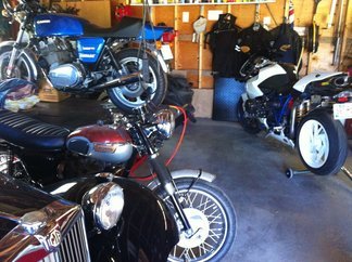
Not a Formula Paul, just a 4c Mirage ( probably came over in the same batch as you black '79 when Franco Romanelli was importing them)) shown sitting on the lift waiting to get an andychain camchain installed. Hope the picture attached(twice I see). Have been trying to get to Wolfgangs a few times but never works out, 'so many things to do, so little time', besides Nakusp was sold out weeks ago. One of these days I'm going to drop in on you and check out your  collection.

Stu
 

Attachments

  • rsz_1rsz_074.jpg
    rsz_1rsz_074.jpg
    46.2 KB · Views: 19
  • rsz_1rsz_074.jpg
    rsz_1rsz_074.jpg
    46.2 KB · Views: 12
Paul LeClair said:
I used professional connectors ...

I knew you'd get there in the end - it's only logic after all  :D

I kind of hate to say this after you've sweated so much blood over this little project, but those aren't professional connectors. Any professional who uses those pre-insulated connectors needs a kick in the backside.  Problem is that those hideous things seem to have 99% market penetration. It's all you'll find in car accessory and hardware shops.

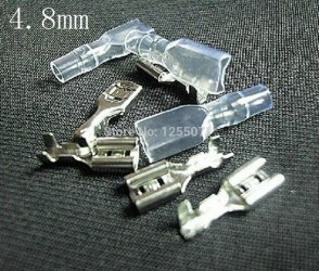
What professionals use is shown below. They have a flexible (looks like silicone rubber) sheath that you slide onto the wire first. You slip the sheath back over the terminal once you've crimped and/or soldered it onto the wire. The flexible cover is neater and provides better support to the cable so you're less likely to get breakages at the transition between floppy cable and solid connector.

I dunno where you'd find them in Canada, but here in Tasmania I have to go to an electrical industry wholesale provider to get them in packs of 100 (Ashdown and Ingram if anyone in Australia is looking for them). They cost something like $5 per hundred, but can be found on ebay in smaller quantities if you only need a few. Let me know next time you're doing a wiring job Paul and I'll send you a handful. I have spade and bullet connectors in stock, as well as ring terminals (6mm hole) for ground connections.

Cam
 

Attachments

  • spade connectors.JPG
    spade connectors.JPG
    96.8 KB · Views: 10
Dellortoman said:
I knew you'd get there in the end - it's only logic after all  :D

I kind of hate to say this after you've sweated so much blood over this little project, but those aren't professional connectors. Any professional who uses those pre-insulated connectors needs a kick in the backside.  Problem is that those hideous things seem to have 99% market penetration. It's all you'll find in car accessory and hardware shops.

What professionals use is shown below. They have a flexible (looks like silicone rubber) sheath that you slide onto the wire first. You slip the sheath back over the terminal once you've crimped and/or soldered it onto the wire. The flexible cover is neater and provides better support to the cable so you're less likely to get breakages at the transition between floppy cable and solid connector.

I dunno where you'd find them in Canada, but here in Tasmania I have to go to an electrical industry wholesale provider to get them in packs of 100 (Ashdown and Ingram if anyone in Australia is looking for them). They cost something like $5 per hundred, but can be found on ebay in smaller quantities if you only need a few. Let me know next time you're doing a wiring job Paul and I'll send you a handful. I have spade and bullet connectors in stock, as well as ring terminals (6mm hole) for ground connections.

Cam

Hi Cam, and all

I used the retail blue plastic covered connectors just for the relay connections and a couple of other spots. Everything else looks like the bare crimp connectors in your photos except without the silicone rubber sheath. When I did the total re wire of the Triumph Spitfire I bought the proper special crimping tools and commercial quantities of all types of connectors, I have quite a stock. I'll ask at my electrical wholesaler for the silicone sheathed ones, although I have never seen them there.

Going for a test ride as soon as I can get a registration plate and insurance on the bike, likely Tuesday at the latest, and start the de bugging/shakedown process, so far I already know that the brand new left petcock and filter must be clogged from the residue left from cleaning the inside of the tank, I am only getting fuel out of the right petcock to the clear external fuel filter on that side, nothing at all to the clear fuel filter on the left side, so I am going to have to drain the entire (presently full) tank to remove the left petcock and clean it and it's filter out. I am sure there will be more small things, I particularly want to know if the bike will shift into all 5 gears, for example.....

I also need to find a side stand to bolt up to the side stand conversion kit I have mounted, which side stand do I need? Kawasaki ZX 6 or something like that I gather? What years will work? Anyone?

Paul LeClair
 
Yep. Kwak ZX6 or ZX12 side stand will do. I've used both on Laverdas, they're pretty much the same length, same mounting bolt centres, etc. (my Jota has ZX12). There's probably a whole bunch of Kawasaki models that use the same stand.
I've got a ZX6 stand on my MHR Ducati too. Invented an adaptor bracket similar to the Laverda one.
 
back to wiring horns with relays......

so, after I added the relay into the horn circuit on the 82 1200, I tested the horns on the 84 RGS and on the 79 1200. Neither have ever been very loud, and they still were not very loud. Tested the voltage at the horns at each bike, each bike had around 7.5 volts at the horns.

so, added a relay into the circuit on the RGS. Ran a separate ground wire from each horn to a nearby grounding point. Then ran a single power wire to each horn from the relay out terminal (87). Instant 12 + volts to the horns, instant super loud horns.

just doing the 79 1200 right now, adding a relay into the horn circuit.

interesting to note. The stock wiring on each of the three Laverda triples for the horns has been completely different between the 79 1200, the 82 1200, and the 84 RGS 1000, but all with the same crappy stock result, losing at least 5 volts or more of the stock 12 volts en route to the horns. The conclusion I have come to is the easy way to trigger the relay is just find where the horn wiring comes out of the wiring harness, tap into it there to use as the switching circuit for the relay (85 and 86), then run a brand new power wire from the relay (87) to each horn, with a separate ground wire from each horn direct to a separate ground. Feed the relay to terminal 30 with a heavy duty power wire with an inline fuse. Problem solved, with the added benefit of no more constant power to the horns whenever the ignition is on, power from the relay only goes to the horn when the horn button is actually pushed........

Paul LeClair
 
Excellent result Paul; have bought all the necessary to do the same on the yellow peril, now you have given me the incentive (kick up the bum) to get on with it. :D
 
Exactly my findings.
7V at the horns even after cleaning all contacts in switch, horn and inside headlamp shell.
A horn relay is definitely the way to go and much cheaper than buying new horns to try to improve matters.
 
Guess not even Laverdas were built to last forever...

When everything is new and shiny, and not corroded and crumbly, the electrics work just fine in stock form!

piet
 
sfcpiet said:
Guess not even Laverdas were built to last forever...

When everything is new and shiny, and not corroded and crumbly, the electrics work just fine in stock form!

piet

yes, I agree. Speaking of crumbly wires, "while I was at it" doing the horn relay install on the RGS I found the small wiring harness from the fuel tank sender to the bike had completely deteriorated to crumbly dust, I guess from the heat of the engine over all those years. Made a new sub harness, fuel gauge seems to be working again......... 8) :o

Paul LeClair

ps Grant, too late for me for the relay to be a cheaper fix, I had already bought brand new horns before I figured out for myself the voltage drop issue.
 
Very interested to read about this relay solution...paid a dealer to sort this on my Jota but they didn't...well, they work when engine running, hardly at all when not.battery v strong.sounds like the same voltage drop issue. I dunno how to fit a relay though...time to bother Clem  ;)again!
 
relays are simple they are a way of switching  a current by remote control, so you have an in (from the switch) and an out (close to, a going to, the horn)
 
The relay is more tolerant of reduced voltages than the horns.
It allows the horns to receive full voltage.
 
horns ??  i hate 'em with a passion!  >:D
horns are always getting in the way of some task and they look bloody ugly.
sitting on a shelf , i have a good set of Fiamm horns, complete with relay, that were the first items removed from SeFFie, my SF2.
& saved about a kilogram of weight.

yes, a horn is required by law, so my option is a trip to the local wrecker to procure a shoddy little cheapo horn.
it's been neatly tucked away, hanging under the battery tray, out of sight and out of mind. 
however, it does make a barely audible squeak, so it meets the legal requirements.
& i don't believe it would tax the voltage feed from the horn button, as it would be barely capable of drawing a full amp with a marker pen ??

just saying, there's always other options.
 
markQLD said:
it does make a barely audible squeak, so it meets the legal requirements.

Not much good around my way! The foreign truck drivers require an ear-splitting blast and ideally some machine gun fire to make them give way - they don't give a shit about little old me on my bike!

VW had an obssession years ago with relays (perhaps they still do?), eveything is fine until they go tits up eventually.
My daughter got into the Golf one day and straight away the indicators wouldn't work! Turned out her schoolbag had dislodged a relay under the dashboard - fff
 
Paul, with the voltage drops you've measured there, it seems that you are in need for a new wiring loom at least. With age of 30 to 40yrs, the copperware is usually heavily corroded and the relays might be only a short term fix, as already mentioned by Piet. When restoring a bike, I always replace the wires, there's no fun in fighting electrical gremlins all ride long.
 
Gravelroad said:
Paul, with the voltage drops you've measured there, it seems that you are in need for a new wiring loom at least. With age of 30 to 40yrs, the copperware is usually heavily corroded and the relays might be only a short term fix, as already mentioned by Piet. When restoring a bike, I always replace the wires, there's no fun in fighting electrical gremlins all ride long.

very good point. When I did the rebuild of my 1972 Triumph Spitfire car I replaced the entire wiring loom with an upgraded and modern design using better wire, better circuitry, better fuse panel, and a bunch of relays.

as I rode various Laverda's when they were new. I guess in my mind they are not all that old yet......... ;) I will have a chat with Wolfgang at his rally shortly about the new wiring harnesses he makes and see what is available for the three different bikes, all triples, but the wiring harness appears different on each, from 79 to 82 to 84.

Paul LeClair
 
I've removed some fairly noticeable voltage drops by replacing the fuse box to modern blade type, key switch rebuild or replace.  Then working up through each and every connector block. if any of the spade ends had any croshion showing clipped 5mm to bright inner core and replaced endes. Time consuming but had results. I still put in relays and have the harness mainly run control power to the relays.

From earlier discussions each coil draws 3-4 amps plus head light 60W 60/12=5amp ~ 3*4A+5A=17Amp and the late model key unit is only a 10 amp unit so they tend to have trouble. The early Nail Key switch on the SF750 was rated at 30amp.

Jugs
 
horn button theory 101
yes, i have consumed a significant amount of time to get Laverda horns to operate correctly.
no, not my Laverda's, but other people's Laverda's.  & no, i'm no expert.

& once again i commend Paul for his determination and achievement to get the job done.  (bigthumb)
& there's a lot of good advice contained in this topic.
i agree that fitting a relay is a good idea, however, i(we) have also successfully got horns to function correctly, several times, without the need to fit a relay.

the 1st step is to provide a good earth to the LH switch-block housing, and this has already been covered, earlier, in detail by others.
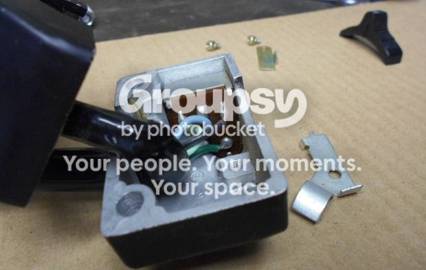
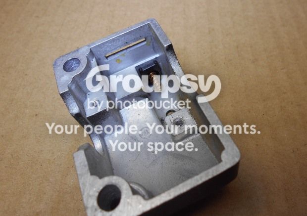
however (imho), one of the weakest links in the horn button earth circuit is the contact(or lack of) between the internal folded switch 'shell' and the LH switch-block housing. Paul commented on this earlier, after his detailed examination;
Paul LeClair said:
.. Following all the circuits back, the grounding originates from the push of the horn button on its tiny brass pin making connection through the even tinier spring on the brass pin, to the body of the combined turn signal/horn button framework, which then grounds to the switch housing. .. 

there should/will be a problem if the switch-block has been refurbished and the housing has been painted internally as well as externally.  internal paint is bad. very bad.
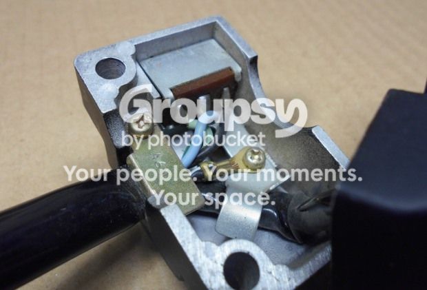
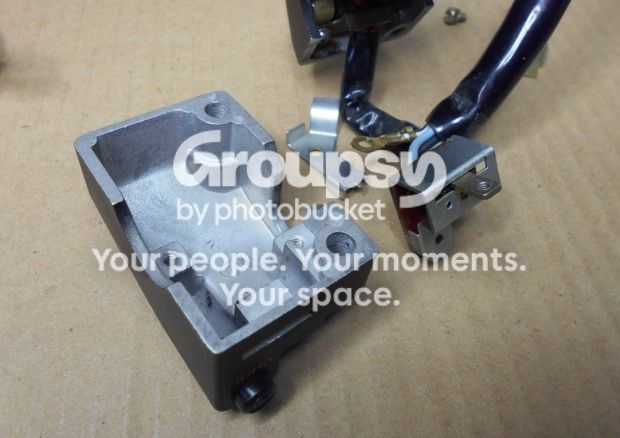
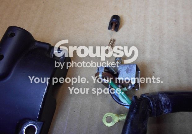
there is no direct electrical connection or flow-path between the internal folded shell and the housing. the indicator/horn switch shell just 'rests' inside the housing and it's held in position by a flat tang that locates into the insulated backing plate. this tang is fastened to the lower housing with the black/white earth wire lug. but this tang can't provide an earth to the horn button because it slots into the insulated backing plate.
i note that, the indicator/horn switch doesn't just fall out of the housing onto the road, so i suggest that there must be some contact between the shell and the housing.  but!!  is this a good enough electrical flow-path to energize the horns ??
no, i don't believe so, and i'm surprised that any horns can function adequately.  but, they can & do.

on a recent job, this contact couldn't be restored, and a wire had to be soldered to the top of the shell and the other end of wire, fitted with a small lug, was fastened under the screw that holds the tang and black/white earth wire lug.  it worked good & no relay was needed or wanted.
the fitting of a relay, in most cases, removes the need  for a 'good' electrical connection between the switch shell and the housing.  but be aware, that to energize a relay, there still needs to be a 'decent' electrical contact between that folded shell and the housing.

this issue hasn't had much discussion, so thought i'd throw it into the mix.
have fun.
DSCN0800_02.jpg


DSCN0801_02.jpg


DSCN0810_02.jpg


DSCN0833_01.jpg


DSCN0815_02.jpg


DSCN0839_01.jpg


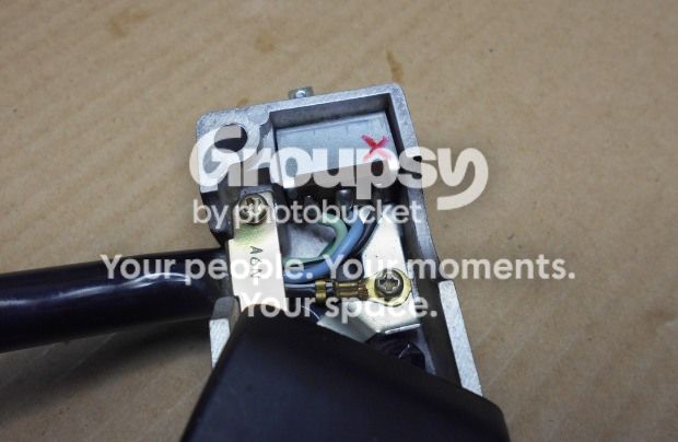
re: recent job mentioned above; the end of a wire was soldered to the shell (at red cross) and the other end of wire, fitted with small lug, was fastened under the screw with the other earth wire lug.  worked good. horns were loud.
DSCN0830_02.jpg

& care is required, with soldering, to prevent frying the indicator switch.
we slid the indicator blade across to the opposite end to where we were soldering.  thanks Bruce.  (thumbup)
 
Back
Top