Ignitech TCIP4 individual advance correction failure

Max, I rephased a stock SF crank for a friend many years ago - counting the number of splines I calculated that the closest I could get was 88 deg (simple 360 deg divided by # of splines). I do have an SFC crank and it's not that easy to get a perfect 360 or 270 or whatever you're chasing - unless you're Red and have a beautiful jig that holds things in place while the press does its work!

I was very careful doing mine and was chuffed when checking with a piston stop and degree wheel that it's as close to 90 deg as I would ever want. But had it not been, it would have been nice to be able to correct the diff in the Ignitech software. In FBG's manual he actually mentiosn the correction factor is useful for this very purpose.
Agreed, but my crank was 1 degree out from the factory! I first modified a standard points plate, next used a Microsquirt controller and then Ignitech, but I don’t recall any timing issues. Maybe the older code worked or I didn’t notice…
 
Max, I rephased a stock SF crank for a friend many years ago - counting the number of splines I calculated that the closest I could get was 88 deg (simple 360 deg divided by # of splines). I do have an SFC crank and it's not that easy to get a perfect 360 or 270 or whatever you're chasing - unless you're Red and have a beautiful jig that holds things in place while the press does its work!

I was very careful doing mine and was chuffed when checking with a piston stop and degree wheel that it's as close to 90 deg as I would ever want. But had it not been, it would have been nice to be able to correct the diff in the Ignitech software. In FBG's manual he actually mentiosn the correction factor is useful for this very purpose.
Just looked up my Ignitech files - no use to you sorry, V88 and I built the offset into the Hall sensors to make programming simple!
 
Just looked up my Ignitech files - no use to you sorry, V88 and I built the offset into the Hall sensors to make programming simple!
Reckon I'll be doing the same - remove and refit one sensor. What type of HE sensor, rotor and backing plate did you use?
 
Soooo… this may be an oversimplification and a product of my limited knowledge and my misunderstanding of Jon’s explanations 😉 but if the system doesn’t allow an “advance” correction, for cyl2, could you (or did you try) retard cyl1 ? Then rotate the backplate to suit?

P.S. if you end up adjusting the physical pickup positions, I was able to correct the same timing issue (on a different machine and not Ignitec) by creating a tiny bit of clearance on the backplate, allowing some sideways movement, then I could move one pickup without moving the other. It was a bit of a pain- microns in it- but it worked, and allowed me to adjust it with the motor running and one eye on the strobe.
 
Reckon I'll be doing the same - remove and refit one sensor. What type of HE sensor, rotor and backing plate did you use?
Will have a look for sensor data sheet and any photos. Will involve beer I think. However, I used CAD to design a new pick-up plate with accurate fixing positions and had it CNC punched. Rotor was locked original advance unit with sleeve grub-screwed to cam, slot to register accurate position, disc with skirt with windows welded to top of sleeve.
 
Soooo… this may be an oversimplification and a product of my limited knowledge and my misunderstanding of Jon’s explanations 😉 but if the system doesn’t allow an “advance” correction, for cyl2, could you (or did you try) retard cyl1 ? Then rotate the backplate to suit?

P.S. if you end up adjusting the physical pickup positions, I was able to correct the same timing issue (on a different machine and not Ignitec) by creating a tiny bit of clearance on the backplate, allowing some sideways movement, then I could move one pickup without moving the other. It was a bit of a pain- microns in it- but it worked, and allowed me to adjust it with the motor running and one eye on the strobe.
Yep - tried that. No go. I think Jon is pointing out that elec advance systems work from full advance as a starting point and digitally retard from that point ... so it's actually an electronic retard system ... if I understand correctly Jon?

I did actually observe a slight change by using the micro play in the backing plate Andy, but not enough to get it to 3 deg. I have a second plate ready to go for 'when i get the other SF built' :ROFLMAO::ROFLMAO::ROFLMAO: but I can't try it until I have a motor to try it on. Working on getting the SFQ back running asap.
 
Quentin,

Laverda ports and combustion chambers really are rather dated. I once chatted with a bloke doing lots of flow bench work on italian classics. For a datum point, he'd reference a certain modern (at the time) jap 4-valver being at 100% efficiency. The Laverda triple would come in at around 60% in comparison, the cooking 750s at around 40%... Anyway, this guy managed to lift a Electronica head from close to 50% to around 65% on his scale, resulting in a very considerable HP bump, something to the tune of 85hp and 75 Nm, while still at 750cc! Before and after were like day and night, the engine would pull like a tractor from way down on C5 cams, right through without a touch of peakiness, all the way to the top. Similar to a 120 triple, but quite a bit quicker and louder.

piet
 
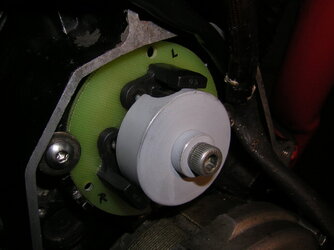
Here’s a crappy photo, and the sensors are OHB900 plus suitable pull-up resistors which I can’t find details on.
 

Attachments

  • Hall2Sm.JPG
    Hall2Sm.JPG
    80.7 KB · Views: 23
Ok Quentin I'll chip in. It's a recognised twostroke tuning technique to extend the power band by dialling in some retard. This increases the temp of the exhaust gas. The speed of sound in the exhaust varies as the gas temp varies. Hotter = faster. So by making the exhaust hotter you shorten the time for a wave reflection to return. Thus making more power past the normal peak
Now this has very little to do with fourstrokes. But the principal of retard = heat still holds.
Hence my suggestion to sort the Ignitech before anything else.

Wearing my fourstroke tuners cap, I would have expected any fuel surge problems on a parallel twin to show on both cylinders. A V twin of course can starve whichever carb is higher.

Yes, different combustion chamber shapes burn at different speeds. A compact chamber will - all other things being equal - need less advance than the "traditional Italian" shapes we see on the 2V Laverdas. And yes, again, I've sorted a piston shape for the 350 road Aermacchi head which only needs 28 degrees advance. The road head is a deep hemi, the genuine factory race head is quite a lot shallower.

I can't point a finger at one thing and say "that caused your blowup" I suspect it was a combination of factors causing excess heat. Once the thermal limit of the head and components is reached there's not a lot you can do except eliminate possible causes one by one.

Piet - Some years back I put an electronic ignition on a 250 Parilla. And yes, I too was surprised at the total advance needed. It had run fixed ignition and was known as a pig to start. C/f advance and a magnetic trigger sorted that.
 
Thanks Greg. I started feeling a tad odd mentioning you in your absence.

Piet, the improvements you mention with the Elettronica are very much in line with what I achieved with the SFQ - what came out surprised the hell out of me. The pull from very low revs and a perfect power curve translates into a very fast bike - yes quicker than any triple it's come near as yet (a Corsa and a Jota) ... and it doesn't make a huge amount of noise. :ROFLMAO: Not sure how a stock SF would pull with 19/36 final gearing ...

While I didn't reshape the chamber, the flat-top piston shape will have had some effect, but I believe it's the work I put into the inlet ports that probably really made the diff - and maybe the smaller ID headers. Larger inlet valves, larger (but not overly) and longer inlet ports, reangled by 5 degrees from a std big valve SF. Final flow work was done by Phil Tainton (knows a thing or two about port shape) - he was impressed with the cut of the seats.

I gave him the head with 10 deg steeper in the inlets but from my own obs it made it almost impossible to get a clean floor on the port. I pointed this out and sure enough the flowbench showed dead air. He reangled BACK to 5 degrees steeper and filled the remaining dip in the floor with epoxy. Said he was very happy with the result. Running a 5C cam. No idea what the efficiency % is, but I'm guessing pretty bloody good. Sure, it's out to 880 but there's a lot more going on than simply larger capacity. By rights 39mm carbs should choke it a bit at lower revs but that's not the case.

Sorry - off-topic from the TCIP4 ... but all very interesting stuff.
 
So have I - and I find it needs replacing about every two seasons. I even drill in from the outside and put in a bent pin as a locator/key.
Maybe singles just shake more......
 
For slotted HE, the shield will be Mumetal, as per URL, does not take kindly to being welded as i saw on one photo.

Yes digital ignitions work on retard only, for iis this was 40dbtdc, if you wanted a 25dbtdc ignition point vector, it will be 40-25 equal 15 degrees retard from 40degrees forward reference.

Points are no different with a centrifugal moving weight system, at full inertial force the points are at maximum Xdbtdc usually 32, as the revs reduce the inertia reduces and the points are counting back from 32 degrees. 32dbtdc is the forward reference. Takes a bit of getting used to "retard" when all you were told "advance" is how it works, you cannot have advance, as your indicating an event in the future, from an event that has not happened, its absurd.

Example, say you have 3 degrees of retarded spark event, from a forward reference at maximum, you then try to advance the retarded spark event by 3 degree, your already at maximum forward reference vector, how can you go past the forward reference? You cannot, that easy. If you were at say 10degrees after forward reference vector, the you could fudge the new spark event by 10-3 ( not 10+3 ) its a negative event when using forward reference vector. That would map, if your ignition control was offering that facility, does it then increase all ignition events down to idle? If so you would then have percentage errors, 3degrees at base idle of say 9degrees would be a 33% error... leave ignitech to support their product, as to what some here are attempting.

In conclusion, no matter what you do to a digital map, if your crank to crank encoder has an inherent error offset, then you may reduce the error up to the forward reference vector, you cannot go past that reference vector, however. All care to make this as transparent as a sheet of glass, you see?... a wry smile here. j
 
Last edited:
Redax will speak for themselves, as i witnessed in company, implemented Bipolar HE, iis used Unipolar HE. Had no need of slotted HE devices, too cumbersome to implement and most notable of all, offered no advantage for dedicated crank shaft encoding. HTH j
 
These pics were sent to me by Jiri at Ignitech - this is the board I use and I modified a similar rotor to work with the SFQ (same sys Lee uses). On the SF it's set up inside out, so all you see from the outside is the backing plate wires exiting. Have had no issues whatsoever with it working - it's the software that bugs me.
 

Attachments

  • Guzzi board & rotor installed.JPG
    Guzzi board & rotor installed.JPG
    88.6 KB · Views: 29
- yes quicker than any triple it's come near as yet (a Corsa and a Jota)
You got ya hand on it Q.......:ROFLMAO:

Forgot to mention the 50kg penalty weight i was carrying! Yes you got the jump but didnt pull any ground up to 190k!
Who couldn't reel in the big black Limo to the Jamieson Brewery (yes i was thirsty).......? made for 880's that rd 💋

Now throw another Slug in that donk and get some ridin in :cool:
 
.....? what is the actual cup rotor made of? Magnetic shutter is no simple fabrication, or proper rotational balance for that matter..... these slotted HE are at least 30+ year old design , if not more... the inter device repeatability is anything but assured. You may well find it is parameter spread at work on the encoder setup shown, if not a mechanical misstep in actual vector position.

Well known in electronics that parameter spread occurs, for many many types of passive and active devices.
Lost for words... yes it happens... said as much as can be useful.... may the first principles deities go with you Quentin. j
 
You got ya hand on it Q.......:ROFLMAO:

Forgot to mention the 50kg penalty weight i was carrying! Yes you got the jump but didnt pull any ground up to 190k!
Who couldn't reel in the big black Limo to the Jamieson Brewery (yes i was thirsty).......? made for 880's that rd 💋

Now throw another Slug in that donk and get some ridin in :cool:
Could well be, Prez! Happy to be proved wrong once I'm back in action :cool: And don't worry - I'm itching to get the thing back up and running. Just don't want to see reconstituted alloy lining my bores again!
 
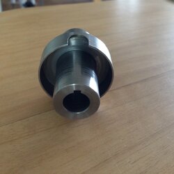
The Moto Guzzi rotor that we use on the Ignitech SF system. It runs off the oil pump drive in lieu of the original points. Ignitech advised me to use this system instead of a crank speed driven one as the Laverda rpm range was not ideal for the induction (?) type triggers. The 270 deg motor has one cutout with two Hall triggers 45deg apart, the 360 system has one trigger and two cutouts.
 

Attachments

  • MG Hall rotor.jpg
    MG Hall rotor.jpg
    226.1 KB · Views: 15
Back
Top