new workshop toy

My reward, thanks Red and Max... but fLIck me it was hard to open, it needs a manual, much like the PP!!! yum yum....

IMAG0039.jpg
 
final shots and report of the Dyno set up following
after much stuffing around and transferring files between us and Stuska we have the Dyno about 95% complete
been running this 120 engine up until now but I am starting to grow man boobs so pulled it out last night
am loading Davo's 180 engine in today so we can have a proper go

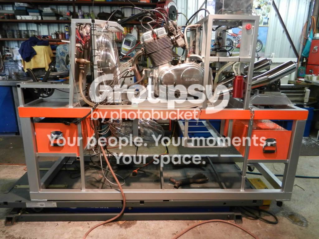
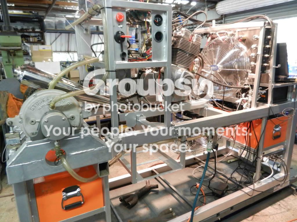
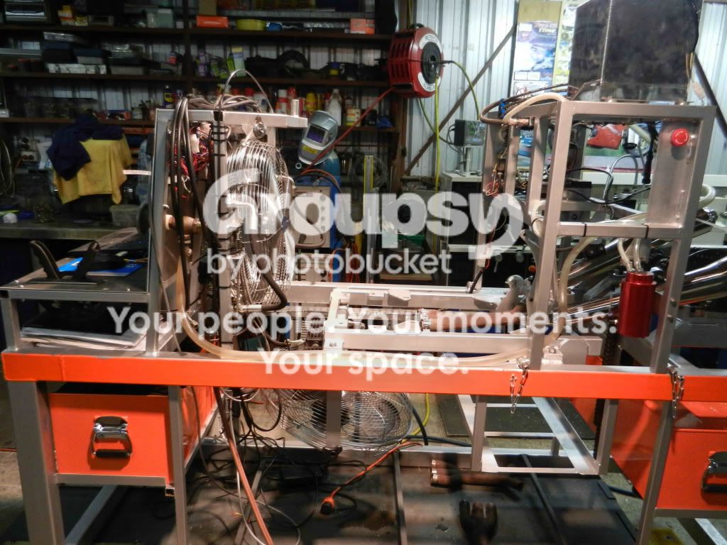
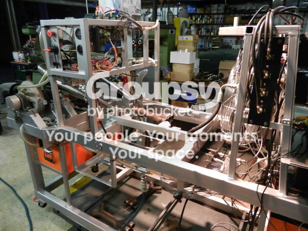
so here are the final 2 shots of the completed Dyno set up

Dyno21stMarch1.jpg


Dyno21stMarch.jpg


what we have found so far
Standard RGS engine, hi Comp 75.5mm Ross Pistons, refurb head but standard valves, etc, running Dellorto's, after running in, leakdown was 2%, 1%, 2% across the 3 cylinders

EGT sensors, at idle, runs about 580C, pull through to 6,000 rpm with reasonable load, goes up to 740C, will go a lot higher under full load but we need to configure the water side a bit more to obtain full load readings, have all 3 running within 20C of each other and they tend to track okay through the rev range

MAP sensors are giving us a hard time, they are too sensitive and are recording everything that is happening which means they are bouncing all over the place to the point I cannot use them for tuning
on Analog vacuum gauges you have the dampening mechanism that you close to steady the needle, don't have that function on digital gauges
we can record what is happening and then when generating a report average a sequence of data points out over a 2 second period which then gives you a steady line but for real time tuning of the engine they are next to useless so am going to mount a set of vacuum gauges specifically to tune the engines

Crankcase pressure is running around 1.9 - 2.4 psi, actually drops when engine is revved which is interesting. I don't really know what this means at this stage, I am planning on recording this feature over a few engines to try and get a base line on what is happening inside the cases. I fully expect that the 180 engines will have a totally different pressure signature
and yes, pressures are correct, pressure module I am using is rated at 0 - 5 psi so is very sensitive

AFR, running on all 3, standard deal, changes as required depending on revs, carb set up, etc

Engine oil temp, having trouble getting the engine oil up to temp, highest seen so far is 75C though as mentioned not gone into full engine loads yet

Dyno speed is working, still playing with engine ratios in the software settings
Not got the Load Cell working yet, Cell itself works but we are playing with restrictor size in the discharge line so we can apply full load to the engine, few more goes yet to get that working, at the moment we are pulling down around 50% load. Also running water feed off the house tap and pressure is too low, need to change over to our 15,000 gal water tank which is beside the workshop, it has it's own water pump which will give me a lot higher inlet side pressure which is what I need

Weather station running, records Humidity, Air Pressure, Air Temp, from that the software works out the SAE correction factors and applies them to the readings

Have 3 x CHT Thermocouples coming from Stuska so am planning on tracking Cylinder Head temp as well, these are set up to be installed below the spark plugs, have a 14mm eye fitting, will be interesting. This will allow me to work out the difference between uncoated engines and engines with the full ceramic package installed

in general, at this stage, am well pleased with results, is up to us now to fine tune the set up and to get to know the capabilities of the Dyno software and how it can help us
one thing is certain, this is a lot of fun when you are running an engine


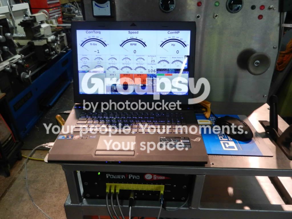
Dynodisplay.jpg


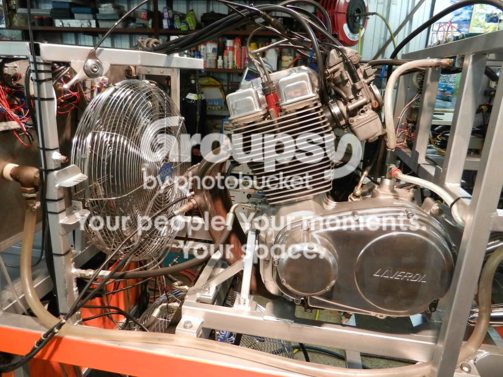
Enginesetup.jpg
 
and this is what is left with engine removed
came out no problem at all, didn't even have to remove the sub frames so am well pleased
we made provision to screw oil lines back onto fittings mounted on the frame so they don't leak everywhere and to keep them clear of contamination
EGT probes have their own holders when not mounted
AFR probes have to be disconnected but they are quick release type anyway
rest just unbolts

pretty well does it for this story, will start a new thread when we get to full engine loads and have something startling to share

BareDyno1.jpg


BareDyno2.jpg
 
Red,

Regarding the MAP pressure fluctuation, I found this also with my EFI.  You just need to put a reasonable volume in the line, to damp out the fluctuations.  As an interim I just got about 5m of vacuum hose coiled up and an inline fuel filter, that damped it down reasonably.  Eventually I made a manifold rail with some volume to it, which sorted it perfectly.  If you intend to use the MAP sensors to balance cylinders, you need one in each line.  Play with the volume till you get a quick response without too much noise.

Awesome setup, well done!  Looking forward to getting up there to have a look/play.

Cheers
Steve B
(who should really be packing for the Barry Sheene)
 
RM and crew,

    Wow amazing machine built by amazing people,  a serious amount of hard work and technology to behold.  Much gawking and dropped jaws from the gallery,  grin.

  Some information that may be of use, or useless...

  Crank case positive pressure(s) on a built motor,  do that here to about 15psi to investigate oil leaks,  regulator feed from compressor to custom oil filler hole adaptor.  Amazing what you discover doing that.  Possible reasons for the Redax dyno ( you named it yet R and M ? )  crank case pressure indications,  analouge to digital interpretations remains a skill for the well experienced.  One of the best approaches is to view the readings from the sensor, via a real time CRO.  Noting any DC bias present ( if a powered sensor ),  watching the actual wave shape from the sensor and noting the digital derived data in real time will allow assessment of the analouge and digital domain signal conditioning being done internal to pre and post display on the laptop, ( just me.. i find laptops to be a second choice for static workstation installations ie the laptop can have more limitations than a tower with remote screen and keyboard ). 

  A switchable signal routing box would allow real time viewing of any and all relevant signals that are crucial to the success of the dyno,  more so as to the map sensor(s),  waveform would be cyclical and irregular in bias i would have thought,  and viewed myself.  The type of map sensor will alter what it is measuring to a little or a great deal,  and this is what real time measurement is all about, interpreting the raw and processed data.  Using the data base of retrieved sensor and performance outcomes ( motor on test ) to establish a base line that determines whether a motor is acceptable or not in performance.

  Think a real time display of the map output ( not on laptop ) would be a very useful, tuning aid, it will show many variables of the operating engine,  valve overlap,  exhaust construction  influence,  etc etc.  Used real time scopes are fairly cheap,  though care needs to be exercised in which one will work properly.  Can drag my Tektronix real time phosor scope up there if of use...  If it were me i would retain the peak readings from the map sensor rather than damp them out, or at least make a switched pneumatic arrangement to damp or not damp the map sensor raw signal,  if that makes sense.

  EGT,  those reading are notably higher than i would have expected and measured have here Red.  About 100C higher in broad estimate of what i read in the posting.  If a non contact professional temperature gun is available i would spot the EGT measure point.  I know it is not gas stream, it will be a useful reading all the same to assess the operation of the sensors involved.  Just quickly are the thermocouple connections and cable,  compensated connections and leads? The correct parent material selected in the data acc. variable,  ie "J" or "K" type etc...  just a bystanders 5C plus gst worth...

  Look forward to seeing the glow from the shed as i arrive.....    john.
 
I can borrow a scope pretty easily, would think it would work by triggering it off the ignition or tacho signal so it has something to grab onto while revs are changing. Mind you the Tektronix are pretty good at finding a trigger in confused signals, better than anything else I've used. Pretty sure the one I can borrow is a Tektronix. Would be interesting to see indeed.
 
Hello Drikko ( where do these handles come from?  ;) ),
   
    Right you are about collecting peripheral data to support main data outcomes,  many is the analouge technique falling by the way side. One of the big problems is lack of analouge chips these days,  the demand is just not there as in decades past.

    Your a canny lad reasoning the TDC is a good place to sync a measurement snapshot, for map readings.  The tacho drive wire on the IIS has a two data output function.  One, frequency output to indicate RPM,  and secondly a two phase related signals,  one edge of the tacho pulse is TDC and the other is 40 degrees post or pre TDC ( check my source code later,  which it is...or "that it be" in old english  ).  The IIS TDC indication is a hard signal ie not a time derived one from a two/three sensor system,  rather 4 sensor on 120 engines with IIS and 3 with 180 engines.  I sense the actual TDC as it occurs or has been calibrated against for that engine.  Found 17 years ago that the crank does not have a uniform velocity cycle to cycle,  it speeds up and slows down.  Without a TDC sensor,  the next approach is to calculate the actual time to arrive at TDC from a forward reference point.  Can work,  though at cold cranking,  the actual velocity is very irregular and therefore time is very non linear.  As rpm rises the error is reduced though it is an "error" in the end.

  Lot going on with a dyno run,  electrical signals from milliVolts to 25KV,  harsh environment to trigger on specific events,  some measuring  equipment excels in this environment and other make more problems than assist.  Some sensors are a balanced signal configuration,  such as proper thermocouple sensor circuitry.  You can use a two channel CRO for that by using CH1 for one signal wire and CH2 for the second signal wire,  then press the invert button CH2 and set the channel function switch to CH1+CH2,  you now have a true differential input CRO,  though the external trigger input remains single ended. Bit of  juggling with the trigger pot and polarity will, if fortunate,  a usable stable display of the monitored signal.  Normal mode and Common mode noise can be a real problem in complex systems, of mixed technologies. Tell me to nick off if all this is known up there...    If needed i have a power monitor scope that can direct connect to the HT points, stand to 25KV or so with 4 differential channels ( Australian designed and built  real time phosphor scope BTW ......so there rest of world....  sticking out tongue... ).  The latter is what i used,  to sort the Poly phase alternator designs for the IIS,  also the revised wiring for bosch alternator coils and proper  RR,  knowledge is all at times.

  Regards to all,  John 
 
redax5 said:
am loading Davo's 180 engine in today so we can have a proper go

or blow it to smithereens...... :o :o :D

Interesting stuff John, once Red has had a while to get it all running properly I'll drag the scope (I checked and is a Tektronix) around and have a look at everything. You can learn a lot by looking at what the analog signals are actually doing.

In the meantime there's some riding and beer to be had this weekend :)

 
EGT,  those reading are notably higher than i would have expected and measured have here Red.

Many moons ago, we measured EGT on my 1980 Jota on a rolling road. IIRC, 720 oC was about the max recorded on centre cylinder using a thermocouple inserted into the top of the exhaust port adjacent to the downpipe when the AFR was optimum.
 
Ok on the EGT,  can only speak as i find and read in technical publications.  If others have different experiences then reading of those differences here is a useful process.  Seen the headers glow a dull red on my TLR in low ambient light levels, when stationary idle, which would indicate a higher EGT than on the Laverda triple.  Suppose the caveat is "Dyno" EGT,  ie cooler air mass over the engine and front pointing headers in that airstream, as opposed to real road riding in normal conditions and air.  The temps i measured were road based live riding.  Just a theory. John
 
when we received our first reading from the EGT I actually considered them to be normal range and is what I expected to find
there is a big difference in temperature between measuring EGT which is achieved by having the thermocouple probe sitting directly in the gas stream from the port and measuring the outside of the exhaust pipe with an infrared beam

when we fired this engine up the middle cylinder EGT would track its two mates up to around 380C and then fall back to 180C, using the hand held infrared beam we figured out that the exhaust pipe temp was doing the same so the sensor was correct, we had fuel issues with the middle cylinder. We didn't have AFR working at that stage, was waiting for a file transfer from Stuska
bottom line, EGT reading of 600C, same time, using the infrared gun on the same pipe and at approx the same point, outside temp of the exhaust pipe is ~220C, surface condition of the pipes effects the infrared reading

the Thermocouple probes are as supplied by Stuska, all the sensor package is, they supplied the Power Pro interface box that you see at the front of the Dyno and all of the sensors that I ordered, with the software configured to suit. There was an exchange of e-mails over an 8 week period where we configured the layout, amount of and type of sensors to suit a Laverda engine, then the Interface box was built to suit that package. This is a custom set up to suit a Laverda engine so I very much doubt that we have the wrong type of sensor or it is configured incorrectly

 
All noted Red,  like you,  the actual workshop and road experiences count in the end.  The data capture package your using,  was not aware it was custom ordered and built,  the suggestions of checking various parameters in the package is something done as a matter of easy things first,  did not suggest the probes were wrong at all, merely the scaling factor internal to the capture software as something to check, though your happy with the readings and being the operator, thats that  :).    

 Am surprised by the marked difference between gas stream temperature and the internal probe to surface of header differential. Given the probe is bonded to the header surface, internal and external.  Live and learn as the saying goes for me.   True,  i do surface temperature measurements as bonded internal sensor is not practical for a usual road riding triple.  Moved the measure point on the prototype during road tests,  and noted the, at times highly variable readings.

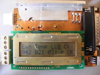
 This is the IIS ignition module with on board EGT circuitry,  used for road measurements,  one of the other features is cylinder head temperature measurement, found the huge commotion going on above on the HT leads could upset the measurement cycle for the digital circuitry coupled to the head or under plug base thermocouple.  Being part of the ignition i could synchronise the measurement of head temp during the "off" cycle of the HT circuitry,   problem solved with some software, nifty.   The signal level from thermocouples is very small and prone to external interference, at times, at least it is a low impedance circuit which helps clobber the external noise or interference.

 Mention the above more as a use or not,   to possible unwanted operation and measurements in new complex equipment and measurements,  well that is no news to you,  drilling equipment is something else to deal with and operate.....

Added later to post;

This web site ( URL below ) has been my mainstay for definitive practical engineering on air cooled engines, these last 8 years or so.  It has been responsible for the leaps of engineering on the IIS.  So may old wives tales and folklore are reduced to the true worth,  nothing.  For those motivated to the nth degree, i recommend every pdf, in particular i draw attention to the Ignition Dynamics 1,  the graphs on EGT are telling plotted against mixture and many other variables.


http://cafefoundation.org/v2/research_reports.php

Regards to all,  John


Attachments

  • 2009_0112IISTB1200001.JPG
    2009_0112IISTB1200001.JPG
    181.5 KB · Views: 10
IIS said:
  Am surprised by the marked difference between gas stream temperature and the internal probe to surface of header differential.

Me too John.

I actually did my engineering thesis on this very subject. I was trying to develop an algorithm to work out the fluid temperature in a pipe by measuring the external surface temperature. After many hours in the thermodynamics lab, it all boiled down to there not being enough temperature difference to need any clever algorithm. The surface temperature was near enough to the fluid temperature, so that one was a close enough estimation of the other for all practical purposes. Furthermore, it didn't make much difference whether the pipe was insulated or not. Admittedly I was using liquids rather than gases, so there  would be different thermal properties involved, but in turbulent flow I wouldn't have expected that to matter too much.

Red's EGT measurements are somewhat surprising. Maybe there's some more complex thermodynamics going on in the pipe, like laminar flow with significant temperature gradients across the pipe, or some combustion flame fronts in the headers. There's also the possibility that one of his thermocouples is fucked. Not to mention the very likely conclusion that I'm a lot dumber than I think I am and I'm talking complete shit  :D

Cheers,
Cam
 
Back
Top