No spark diagnostics

I'm assuming that the ignition circuit (not just the relay coil) is already protected by a fuse so there's no point in adding another.

Relay just puts a lot more potential points of failure in a circuit...connections; coil; contacts plus wiring.  Should only be used where there is a real benefit.  Motor manufacturers go to a lot of trouble to minimise starter & ignition wiring for obvious reasons..  The Ignitech takes the square root of bugger all current and is volt-drop tolerant, so direct connection is fine.

Why you don't want a load of these ...
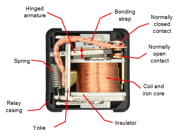
Inside_of_automotive_relay_large.png
 
Grant said:
What the hell does that mean?

There's four buttons on the test tab of the Ignitech software that seem to test whether the unit can trigger the coils. When you press the first two there is a sound like a spark. Simple troubleshooting tool as far as I can tell.
 
instead of listening for a spark it is far better to earth a set of plugs out on the engine cam cover and that way you can watch for the spark

 
there is a sound like a spark

Get a sparkplug and connect it up to each HT lead in turn, lay them on the cylinder head and test fire them.  You want to be able to see a big fat blue spark to be sure it's all working.

A weedy spark is no good - I had this trouble with my old bike before I binned the original ignition, drove me demented - had a spark but not enough to fire the bike up.
 
Yes I unplugged the leads, then earthed a plug in one of the leads against engine whilst hitting the engine start button. There was spark from all three.

That said I wouldn't describe it as a strong blue spark but I was using an old Iridium plug to test with.


Rob said:
I'm assuming that the ignition circuit (not just the relay coil) is already protected by a fuse so there's no point in adding another.

Relay just puts a lot more potential points of failure in a circuit...connections; coil; contacts plus wiring.  Should only be used where there is a real benefit.  Motor manufacturers go to a lot of trouble to minimise starter & ignition wiring for obvious reasons..  The Ignitech takes the square root of bugger all current and is volt-drop tolerant, so direct connection is fine.

Why you don't want a load of these ...
Inside_of_automotive_relay_large.png

The only fuse on the ignition circuit was linked to the relay. So if the kill switch and coil power comes through that same fuse box then that should work.

It seems like there was a combination of factors here. The lose earth had an impact, the relay also seems to have played a role. The wiring wasn't bodgy ,previous owner was very diligent, it was just a little over engineered.
 
That said I wouldn't describe it as a strong spark.

I seem to remember John Wilson (he of IIS ignition fame, sadly NLA) said his boxes would produce a spark that would easily jump 5mm or more.  Certainly a properly functioning modern ignition should produce a big, fat, blue spark.  Doing a test firing on the IIS sounds like you have a nest of hornets inside the motor when it gets to 8000rpm or more.
 
with interest i pose the question as to why you are fucking around with ignitech software when it seems quite apparent that you have a sashe ignition box?
 
Reggie3cl said:
I seem to remember John Wilson (he of IIS ignition fame, sadly NLA) said his boxes would produce a spark that would easily jump 5mm or more.  Certainly a properly functioning modern ignition should produce a big, fat, blue spark.  Doing a test firing on the IIS sounds like you have a nest of hornets inside the motor when it gets to 8000rpm or more.

ANY modern ignition should throw a spark of at least 5mm.  I've tested DMCs capable of jumping 8-9mm.

But you can't extract more than your input...

piet
 
IIS systems had by far the best test circuit of all the after market ignitions available, idea was to cut the tangs off of 3 plugs which effectively increase the plug gap
earth them on the cam cover, select test mode on the IIS box, turn ignition on, ignition would start to spark at 1,000 rpm and then increase in intensity by ramping up to 10,000 rpm in steps of 1,000 rpm per step
with the increased plug gap you effectively apply an increased load on the ignition system itself and was simple to diagnose faults, dud coils, bad leads, etc

John is still around, been swapping emails with him last few days, he has happily morphed into an old bass playing hippy  :o

 
Cosi said:
with interest i pose the question as to why you are fucking around with ignitech software when it seems quite apparent that you have a sashe ignition box?

I'll.let someone else jump in on that one.
 
Cosi said:
with interest i pose the question as to why you are fucking around with ignitech software when it seems quite apparent that you have a sashe ignition box?

Carlo has an Ignitech box on his bike, don't get mixed up with the photo Grant posted showing a Sachse box


Vince said:
The bolt is a left-hand thread, if you dont have a rattle gun try hitting a big shifter with a hammer to shock the nut off, in the correct direction. Screw the puller onto the big outer thread to you get a good connection and then wind in the bolt to push the flywheel off. Don't lose the woodruff key, that's the sliver of metal that goes into the slot on the shaft locating the flywheel. Nobodys BORN knowing this shit, give the flitten bloke a break, help if you like or FUCK OFF if you don't.

Not on Carlo's bike Vince. He has a Redax alternator which uses a 3-legged puller.  Triangular plate with 3 bolts that screw into the alternator rotor and a central bolt that bears on the end of the crank.

Anyway, he's getting a spark when cranking the engine so the pickup board appears to be working.
 
Well I can confirm that she started first time.
:D :D  :D

So off to get some suitable connectors etc then I'll take it to my local guys next week and get them to check what I've done.

Thanks again for the ongoing help. I know it's frustrating trying to troubleshoot remotely (I remember trying to get my Mum in the UK set up on Windows 10!!) but this one was an unholy combination of wiring and software


cbertozz said:
So off to get some suitable connectors etc ...

Hey Carlo.

As you're something of a novice at this auto electrics business, here's a couple of tips about cable connectors:

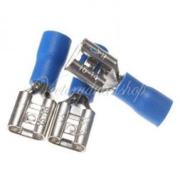
Don't get the pre-insulated connectors with the coloured plastic collar around the part to be crimped (like the blue ones in the photo below). They're rubbish, but seem to be ubiquitous in hardware and car accessory shops.

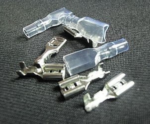
Get uninsulated connectors with separate soft plastic covers as in the middle picture below. Slip the insulating cover onto the end of the wire, crimp the terminal on, then slide the cover back over it. This type of connector is a little harder to find. You need to go to a specialist electrical supplier or buy them on line.
Suppliers such as Ozautoelectrics sell them
http://www.ozautoelectrics.com/narva-56244-blade-terminal-insulators-suits-6-3mm-female-56224-pack-of-100.html
http://www.ozautoelectrics.com/non-insulated-female-blade-crimp-terminals-qk-series-tin-plated-brass-6-3mm-tab-0-8-1-5mm2-wire-size.html

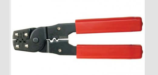
You also need a proper crimping tool, like the one in the bottom picture at the very least. More fancy ones are available, but for your purposes the one shown is adequate. If you try to crimp with pliers, it won't crimp properly but you can solder it to make it work.

A set of wire stripping pliers is also handy if you're intending to do lot of this stuff.

Cam
 

Attachments

  • rubbish connectors.JPG
    rubbish connectors.JPG
    26.4 KB · Views: 7
  • good connectctors.JPG
    good connectctors.JPG
    77.1 KB · Views: 10
  • crimp tool.JPG
    crimp tool.JPG
    25.7 KB · Views: 7
I have the same flywheel and puller, was doing it from memory and was just a bit pissed off at the peanut gallery at the time. It was pretty obvious to me Carlos was giving it a red hot go and was low on his learning curve, and didnt need any more kicking while down. I will leave it there as I have some brake pads to replace.
 
Dellortoman said:
Hey Carlo.

As you're something of a novice at this auto electrics business, here's a couple of tips about cable connectors:

Don't get the pre-insulated connectors with the coloured plastic collar around the part to be crimped (like the blue ones in the photo below). They're rubbish, but seem to be ubiquitous in hardware and car accessory shops.

Get uninsulated connectors with separate soft plastic covers as in the middle picture below. Slip the insulating cover onto the end of the wire, crimp the terminal on, then slide the cover back over it. This type of connector is a little harder to find. You need to go to a specialist electrical supplier or buy them on line.
Suppliers such as Ozautoelectrics sell them
http://www.ozautoelectrics.com/narva-56244-blade-terminal-insulators-suits-6-3mm-female-56224-pack-of-100.html
http://www.ozautoelectrics.com/non-insulated-female-blade-crimp-terminals-qk-series-tin-plated-brass-6-3mm-tab-0-8-1-5mm2-wire-size.html

You also need a proper crimping tool, like the one in the bottom picture at the very least. More fancy ones are available, but for your purposes the one shown is adequate. If you try to crimp with pliers, it won't crimp properly but you can solder it to make it work.

A set of wire stripping pliers is also handy if you're intending to do lot of this stuff.

Cam

Thanks Cam. Noted. I dont want any more issues if I can avoid it. I have a crimping/stripping thingo like the one you have in the pic but I'll get the connectors.
 
Rob said:
I'm assuming that the ignition circuit (not just the relay coil) is already protected by a fuse so there's no point in adding another.

I don't think it is safe to assume anything with the wiring on this bike  :o
 
cbertozz said:
How about you come and give it the once over when its done?  ;) (I'll even buy you a coffee!)

I run out at $200 an hour so that's a shitload of coffee  :LOL:
 
Back
Top