RGS1000SFC Engine Case Split

The saga continues...

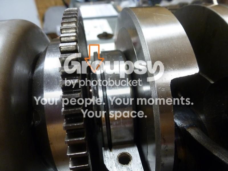
Split the cases and extracted the crank and lo and behold, the end bearing spacer (that half-round bit) was missing from the alternator side of the case!  Luigi?  Previous owner?  No damage evident. 

Anyway, while it was apart a close inspection of the bottom of the case revealed no loose bits like pieces of chain, sideplates, washers, old dirty rags, Jimmy Hoffa, etc.  So, now that all is Timeserted properly, the engine gets re-assembled and re-installed with new studs all around (thanks Wolfgang!).  Hopefully, a resurrected RGS1000SFC will be making beautiful music soon, thanks in large part to this forum!  More to come...I am certain.

 
If you have Timcerted all the M9 studs, then when building the motor, only install two on the carb side at the furthest corners, this makes dropping the cylinder block onto the pistons and ring clamps a lot easier, also don't install the cam chain.
The stud heights are as follows, measured from the top face of the cylinder block with it installed with all pistons rings etc and those two loose studs, make sure the block is nicely seated on its gasket, the proceed to install the studs in the right places (six long one are for the cam bearings, when the head goes on)
short 9mm studs protrude above joint face 101mm
long 9mm studs protrude above joint face 134mm
7mm studs (2 only) protrude 89.5mm above joint face (you did Timcert these as well didn't you?)

Then fit the head and torque in 5ft/lb increments in the correct order,( be sure your torque wrench is a good one and  can go no higher than about 40 ft/lbs)
it doesn't matter if any of the studs feel "loose" after you have Timcerted them, when the nuts and washers are on the ends that will all lock itself up, the  7mm and 8mm ones usually bottom out though.

once the head is on with the cams and bearings, then lay the motor onto all four of the gearbox mounts so that the bottom of the case is faces you, then get two pieces of straight welding rod (1/16th is ideal) bend the ends over 180 degreees and flatten, to make a "nose", create a hook at the other end and attach the cam chain, now fish the chain up the tunnel starting at the bottom, through the cam pedestal port hole, one side is a cinch, the other side has a slight bend to it, pull the ends out, at the top of the motor, then turn it around and join the ends with the crank and cams both in the correct position and get the link on the correct side and correct direction,, when joined, be sure to check (using a torch) that the chain is on the crank sprocket and not sat beside it, now you are nearly there.
CLEM


The six 8mm studs (which still have 13mm AF hex nuts) should protrude 39.5mm above the head face that they protrude through or close to it if bottomed, these are torqued to a lesser spec, most manuals have the torque figures wrong, I always use 28ft/lbs for the 9mm ones and 15 ft/lbs for the 8mm ones
 
MAny thanks, Clem.  Very thorough explanation.  Helps, a lot.

One question, though:  Why put the camchain in after the head is on?  Seems simpler to fit it when the crankshaft gear is easier to access, before the top case goes on.  Not having done this before, the logic is obviously escaping me at this point.
 
each to his own, I don't like having the ends of the chain flopping around as I lower the cylinders on, or the head, and the risk of dropping one end or both ends down the tunnell, I have been doing it the chainless ways for years and much prefer it, its just something else that is not in your way, and since I am a welder I have ready access to nice straight,fairly hard (sixteenth of an inch) welding rods, although I do keep a set ready for the job which I recycle a few times, not tight, just eco friendly.
CLEM
 
Chain-first way ensures the chain is correctly on the crank sprocket.
It IS possible to install the chain to one side of the crank sprocket, be able to join the chain and even run the engine.
The side plates on the chain will butt up to the crank sprocket and it will drive the cams.
For a while.

DAMHIK..........

Then again, you will only do it once.
 
you are not wrong Grant, but re read the last few words of my post above before the signature.(Aug 14th)
There are two good ways of doing it, the choice is which would you find easier?
CLEM
 
Agreed Clem, but I find it easier and safer installing it as I fit the crank into the lower case.
One time I dropped the chain down the cam tunnel (some years ago) and fished it back up with straightened coat hanger wire. Joined the chain up, refitted the engine and used it for 2 weeks before the chain snapped, bending some valves.
The chain had been sitting between the crank web and the crank sprocket, being driven off the chain side plates.
Ever since then I prefer fitting the chain as I go.
Easy technique to master, even on my own.
 
Get yourselves one of these...

http://www.ebay.de/itm/53092-Engine-or-Gearbox-Stand-with-450kg-Maximum-Capacity-/281342106307?pt=UK_CarsParts_Vehicles_CarParts_SM&hash=item41814bdac3

Usually a drip tray available from the vendors, very recommendable.

Makes fitting the camchain after everything else is buttoned up a doddle, easy to check if it is on the sprocket correctly too.  Only requires a couple of dedicated brackets for the Lav engine, if you're clever, they will fit both twins and triples.

After years of humping the alloy lump around on the workbench, spilling oil all over the place and suffering a hernia every second time, I can say such a stand is an absolute revelation. 

piet
 
could not be bothered setting the cam chain in position when installing the crankshaft, cam chain is just a pain in the butt being in the way while building the rest of the engine
totally agree with Piet but I am still lugging that big alloy slab still, no engine stands yet

here is the way I do it, 5 easy Cam Chain fitment photos

with cylinder head installed but with the 6 x 9mm stub nuts just nipped up, drop the cam chain down the front cam chain tunnel
you want to have approx 100mm of chain left hanging out, tie off with a set of Laverda special issue shoelaces, essential tools for any serious Laverda engine builder
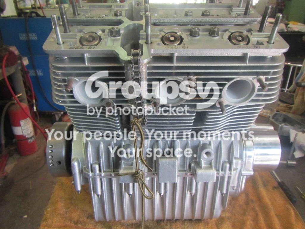


once cam chain is tied off to the front engine bolt hole, spread a nice family towel out behind the engine and just roll that sucker over
using a hooked piece of wire and a torch, fish that cam chain out of its hole and drape over the front of the engine as shown in the next photo
now feed a bowed piece of wire through the other cam chain tunnel so it comes out of the head, in the photo you can see the piece of stainless TIG wire sticking up out of the engine
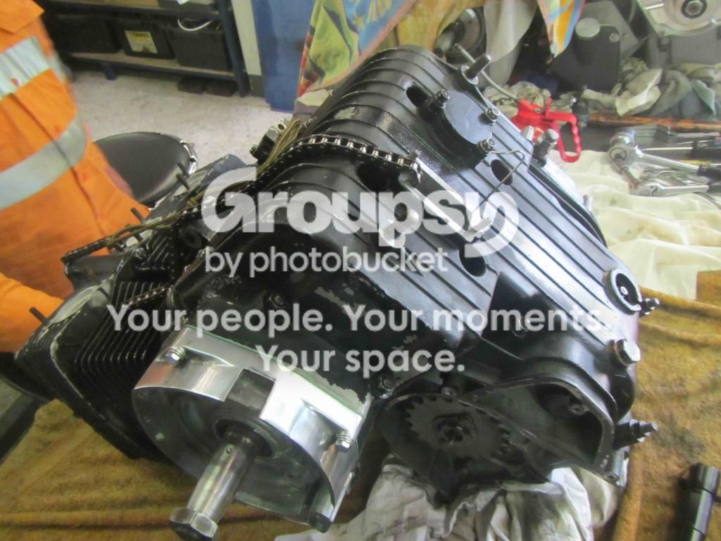


join the wire to the end of the cam chain, make certain to close the wire ends in so the sharp edge does not catch when being pulled through and then pull the cam chain through until it is just shy of the cam chain pillar mount, now grab that second special issue Laverda shoelace and feed it through below the cam chain, this allows you to position the cam chain loosely on the sprocket
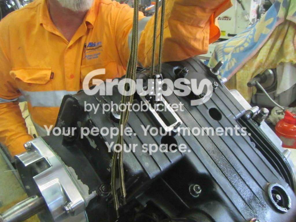


just pull the TIG wire through while lowering the chain into position, use the shoelace to position the chain correctly, it will not at this stage fit properly onto the sprocket due to the shoelace being in the way but once roughly in position, use a large flat screwdriver to hold the chain against the web support, pull shoelace out and chain will drop onto the sprocket, is really a piece of piss to do
on some cranks/web supports you may need to give the chain a sharp tap with said screwdriver and a hammer as they foul on the web support sometimes, takes nothing to get them seated properly, confirm chain is in position by peering down the cam pillar hole with that trusty torch, all looks good in there, install cam chain pillar and button up the rest of the bottom of the engine
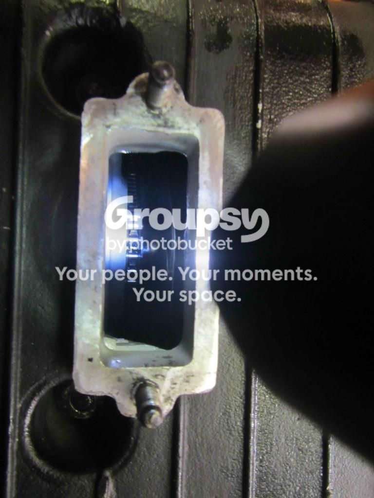


remove the TIG wire from the cam chain, install that 2nd special Laverda issue shoelace, hold the shoelace tight while rolling the engine back over, tie cam chain off to rear upper engine mount, carry on installing the camshafts, etc, join the cam chain
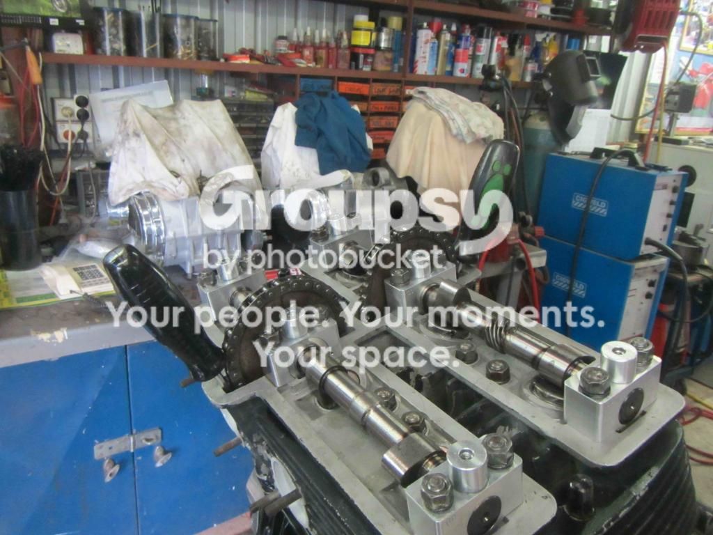


Very nice guys!  All good instructions.  Don't know which way I'll do it, yet.  Maybe try both and see which way I like best!

One question:  Should the crank be positioned so No. 1 piston is at TDC while doing all of this?  That way, when the cams are lined up correctly, the master link will be centered between the cam gears.  Right?

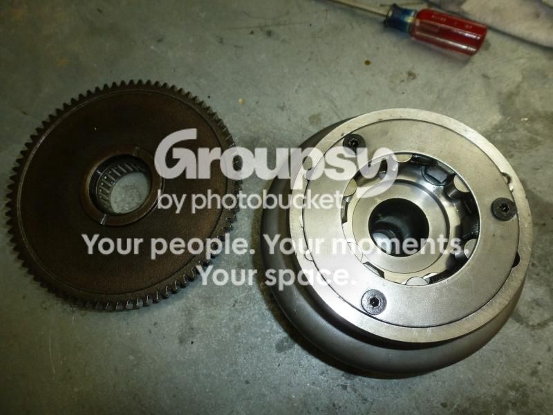
One more, unrelated:  Just got the block back from my consulting machinist with all the M9's Timeserted.  He warned me not to lift the alternator assembly or risk letting the little rollers and springs loose.  I forgot what he had said 30 seconds later and lifted the bugger.  Getting the rollers back in place with the springs was not much trouble, but putting the gear back in while the springs are compressed is a puzzle that is escaping me.  Diabolical, some would say!  :-[

I suppose there is some slick Laverda tool to make this easy.  Not having one of those (if there is one), what is the next best thing?

P1020111_zpsbdf6b706.jpg
 
motoddrob said:
Piece of piss, just rotate the gear clockwise [looking at the photo] at the same time as inserting, should just slip in.
No shit.  Worked like a charm.  Many thanks. Dropped a couple of bearings a couple times, but got it in no problem.  Good thing to know!

Now, another issue?

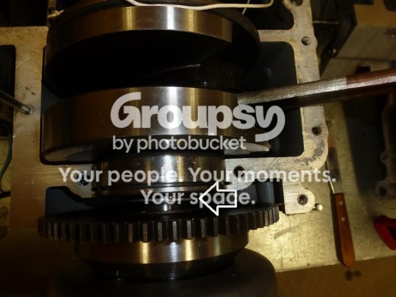
There was a washer between the alternator assembly and the crank when it was disassembled by the machinist.  I didn't notice the clearances when taking it apart, but upon putting it back together, I notice the washer does not take up all the space between the alternator assembly and the crank.  What is it's purpose?  Doesn't seem to do anything since it is not thick enough to take up the space between the alt assembly and crank.

In the photo I tried to show the washer (a bit askew on purpose so you can see it) with the arrow pointing at it, the alternator assembly (bottom) and the crankshaft (top).  Am I missing a part or am I putting together wrong?

AlternatorWasher2_zps2754532f.jpg
 
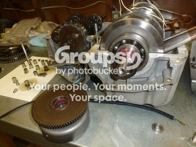
Just in case the last post was not clear, here is the sequence of assembly of the alternator housing I used.

1.  washer on first

P1020115_zps75f7c3ce.jpg


2.  alternator housing assembly next

P1020117_zps6c60958b.jpg


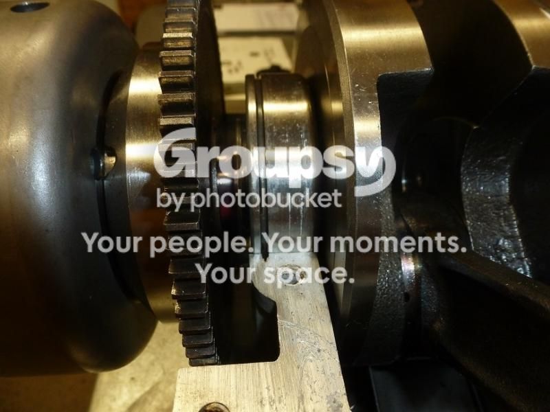
3.  Push up the tapered shaft as far as possible and the washer flops around loose (arrow shows the gap between the washer and the crank)

WasherandGap_zps7af9b40c.jpg


I hope this helps.

S

 
Back
Top