SF1 wiring question

harpmeister

Full member
Location
UK
Could anyone tell me what gauge/amperage of wire should be used between the + terminal on the battery and the regulator then on from the regulator to the ignition switch and back down to the fuse box.

Also on the wiring diagram there is a symbol with the number 18 in it between the front and rear stop switches anyone able to tell me what that is, and while I'm at it I might as well push my luck and see what is the best connecting strip to use to wire everything up to and no the budget doesn't stretch to motogadget.

Thanks in advance

 
Well, it's a bit of an open-ended question. How long is a piece of string?

What's the biggest load hanging off the ignition switch? Probably the headlight, but it's a different story if you're using relays, or a LED light.

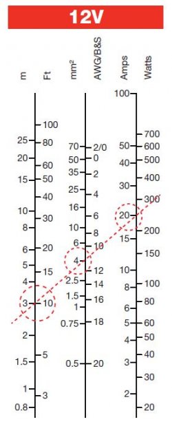
Let's assume a 65/55W headlight with no relays. Chuck in an indicator at the same time and there's another 42W (2 x 21W).  That gives 107W at 12V = 8.9A. If you happen to use the horn at the same time, add another couple of amps. So maybe a maximum load of around 15A. Let's err on the safe side and call it 20A.

Now, how long is the wire between the battery and the ignition switch? Let's say 3 feet.

Refer to the 12V wire size chart below. A 3ft length of wire carrying 20A needs to be 4mm2. So there's an answer to your cable size question, but you might wanna revise those numbers according to whatever your loads and wiring configuration happen to be. You can use the chart to size other wires in the system too.

Your question about connecting strip is also a bit vague. To my mind, a connecting strip is simply a lump of brass with holes and clamping screws to connect a bunch of cables, common in house wiring but not often used in automotive applications. A Motogadget is at the other end of the complexity scale, with circuit breakers and control logic built in. Somewhere in between those two extremes is a fuse box. 4 fuses should be enough for a reasonably simple motorcycle wiring system.
 

Attachments

  • Wire size chart.JPG
    Wire size chart.JPG
    39 KB · Views: 18
Looks like it's gonna be 2.5mm twin and earth and some connector strip

I've seen worse! 

Main fuse is probably 16 amp (but it takes at least twice that before it blows).  Volt drop is the main consideration, so I'd aim for 3mm2 thinwall - rated at 33 amps.  You can read all about cable sizing here https://www.12voltplanet.co.uk/cable-sizing-selection.html

Item 18...may be a diode in the live feed to front & rear brake light switches?

Blade connector strip - 12 way - can be cut down as required https://www.autoelectricsupplies.co.uk/product/48/category/7

Just read Cam's treatise....I'm assuming you're following the original wiring schematic. Intermittent loads are usually derated with a diversity factor applied.  Not sure about the science behind that chart. Cable length needs to be taken to the load and back. And I claim a prize for the mixup between 3m and 3ft.  20A over 3ft doesn't need 4mm cable ... I also doubt 3ft is sufficient!  ;)


Thanks for the replies it has cleared up a couple of points, I suppose what I was asking in a roundabout way was what would it have been wired in originally as the wiring on the bike will remain almost original with no extra accessories etc.

It's a complete rewire as there was very little of the original harness intact and what there was had been played about with a bit and as I want to get it right first time you can expect a lot more dumb questions.

Good link to the 12voltplanet Rob it will certainly come in handy
 
"the wiring on the bike will remain almost original"
If you are rewiring with a copy of the original it is best to use relays for lights (and for myself ignition switch) as the original has many passes through terminals and contacts, all potential power thieves.
 
Back
Top